DTC C0040-16: Plausibility BLS vs. Pressure Sensor
NOTE:
- Troubleshoot any PGM-FI DTCs first - Refer to: How to Troubleshoot the Fuel and Emissions SystemsHow to Troubleshoot the CVT System(CVT System) .
- Before you troubleshoot, review the general troubleshooting information .
| DTC Description | DTC | Freeze Frame |
|---|---|---|
| C0040-16 Plausibility BLS vs. Pressure Sensor |
- 1. Problem verification:
1. Turn the vehicle to the ON mode.
2. Clear the DTC with the HDS.
3. Turn the vehicle to the OFF (LOCK) mode, then start the engine.
4. Wait 1 second or more without pressing the brake pedal.
5. Press the brake pedal hard for 1 second or more.
6. Check for DTCs with the HDS.
DTC Description DTC Freeze Frame C0040-16 Plausibility BLS vs. Pressure Sensor Is DTC C0040-16 indicated?
YES
The failure is duplicated. Go to step 2.
NO
Intermittent failure, the system is OK at this time. Refer to intermittent failures troubleshooting . If the freeze data/on-board snapshot of this DTC is recorded, try to reproduce the failure under the same conditions with the Freeze data/on-board snapshot.
- 2. VSA modulator-control unit performance check:
1. Check the parameter(s) below with the HDS. Do not press the brake pedal.
Signal Current conditions Values Unit BRAKE PRESSURE Is there 8 MPa or less?
YES
Go to step 3.
NO
Check for brake drag or a misadjusted brake pedal height . If they are normal, go to step 12.
- 3. Brake pedal position switch performance check 1:
1. Check the parameter(s) below with the HDS while pressing the brake pedal.
Signal Current conditions Values Unit BRAKE SWITCH Does it indicate ON when the pedal is pressed, and OFF when the pedal is released?
YES
Intermittent failure, the system is OK at this time. Refer to intermittent failures troubleshooting . If the freeze data/on-board snapshot of this DTC is recorded, try to reproduce the failure under the same conditions with the Freeze data/on-board snapshot.
NO
Go to step 4.
- 4. Brake pedal position switch performance check 2:
1. Turn the vehicle to the OFF (LOCK) mode.
2. Disconnect the following connector.
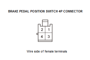
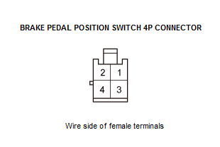
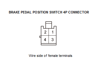
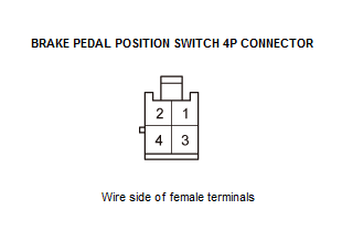
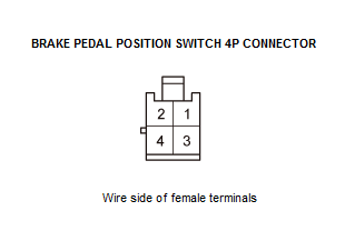
Brake pedal position switch 4P connector 3. Connect terminals 1 and 2 with a jumper wire.
Terminal 1 Brake pedal position switch 4P connector No. 1 Terminal 2 Brake pedal position switch 4P connector No. 2 4. Turn the vehicle to the ON mode.
5. Check the parameter(s) below with the HDS.
Signal Current conditions Values Unit BRAKE SWITCH Does it indicate ON?
YES
Check the brake pedal position switch adjustment . If it is OK, replace the brake pedal position switch .
NO
Go to step 5.
- 5. Fuse check:
1. Turn the vehicle to the OFF (LOCK) mode.
2. Disconnect the jumper wire.
3. Check the following fuse.
Fuse No. A16 (10 A) Location Under-hood fuse/relay box Is the fuse OK?
YES
The fuse is OK. Reinstall the fuse, then go to step 9.
NO
Replace the fuse. If the fuse blows again, go to step 6.
- 6. Shorted wire check (+B STOP line):
1. Check for continuity between test points 1 and 2.
Test condition Vehicle OFF (LOCK) mode Brake pedal position switch 4P connector: disconnected Test point 1 Brake pedal position switch 4P connector No. 2 Test point 2 Body ground Is there continuity?
YES
Repair a short to body ground in the wire between the No. A16 (10A) fuse in the under-hood fuse/relay box and the brake pedal position switch.
NO
The +B STOP wire is not shorted to body ground. Go to step 7.
- 7. Shorted wire check (STOP SW line):
1. Jump the SCS line with the HDS, and wait more than 1 minute.
2. Disconnect the following connector.
PCM connector A (51P) 3. Check for continuity between test points 1 and 2.
Test condition Vehicle OFF (LOCK) mode Brake pedal position switch 4P connector: disconnected PCM connector A (51P): disconnected Test point 1 Brake pedal position switch 4P connector No. 1 Test point 2 Body ground Is there continuity?
YES
Repair a short to body ground in the wire between the brake pedal position switch and the PCM.
NO
The STOP SW wire is OK. Go to step 8.
- 8. VSA modulator-control unit check:
1. Reconnect the following connectors.
Brake pedal position switch 4P connector PCM connector A (51P) 2. Turn the vehicle to the ON mode.
3. Clear the DTC with the HDS.
4. Turn the vehicle to the OFF (LOCK) mode, then start the engine.
5. Wait 1 second or more without pressing the brake pedal.
6. Press the brake pedal hard for 1 second or more.
7. Check for DTCs with the HDS.
DTC Description DTC Freeze Frame C0040-16 Plausibility BLS vs. Pressure Sensor Is DTC C0040-16 indicated?
YES
Go to step 12.
NO
Troubleshooting is complete.
- 9. Open wire check (+B STOP line):
1. Measure the voltage between test points 1 and 2.
Test condition Vehicle OFF (LOCK) mode Brake pedal position switch 4P connector: disconnected Test point 1 Brake pedal position switch 4P connector No. 2 Test point 2 Body ground Is there battery voltage?
YES
The +B STOP wire is OK. Go to step 10.
NO
Repair an open in the wire between the No. A16 (10 A) fuse in the under-hood fuse/relay box and the brake pedal position switch.
- 10. Open wire check (STOP SW line):
1. Jump the SCS line with the HDS, and wait more than 1 minute.
2. Disconnect the following connector.
PCM connector A (51P) 3. Check for continuity between test points 1 and 2.
Test condition Vehicle OFF (LOCK) mode Brake pedal position switch 4P connector: disconnected PCM connector A (51P): disconnected Test point 1 Brake pedal position switch 4P connector No. 1 Test point 2 PCM connector A (51P) No. 37 Is there continuity?
YES
The STOP SW wire is OK. Go to step 11.
NO
Repair an open in the wire between the PCM and the brake pedal position switch.
- 11. PCM check (update or substitution):
1. Reconnect the following connectors.
Brake pedal position switch 4P connector PCM connector A (51P) 2. Update the PCM if it does not have the latest software , or substitute a known-good PCM .
3. Clear the DTC with the HDS.
4. Turn the vehicle to the OFF (LOCK) mode, then start the engine.
5. Wait 1 second or more without pressing the brake pedal.
6. Press the brake pedal hard for 1 second or more.
7. Check for DTCs with the HDS.
DTC Description DTC Freeze Frame C0040-16 Plausibility BLS vs. Pressure Sensor Is DTC C0040-16 indicated?
YES
Go to step 12.
NO
If the PCM was updated, troubleshooting is complete. If the PCM was substituted, replace the original PCM .
- 12. VSA modulator-control unit check (update):
1. Update the VSA modulator-control unit if it does not have the latest software .
2. Turn the vehicle to the OFF (LOCK) mode, then start the engine.
3. Wait 1 second or more without pressing the brake pedal.
4. Press the brake pedal hard for 1 second or more.
5. Check for DTCs with the HDS.
Is DTC C0040-16 indicated?
YES
Check for loose terminals and poor connections in the VSA modulator-control unit 38P connector. If the VSA modulator-control unit was updated and the symptom/indication is still present, replace the VSA modulator-control unit .
NO
Troubleshooting is complete. If any other DTCs are indicated, go to the indicated DTCs troubleshooting.