Engine Compression Test And Cylinder Leakage Test (JA45446)
Reference number: JA45446
ENGINE COMPRESSION TEST AND CYLINDER LEAKAGE TEST
TECHNICAL SERVICE BULLETIN
| HONDA: | All Models |
| APPLIES TO: | L4 Engines |
ENGINE COMPRESSION TEST
- Warm up the engine to normal operating temperature (cooling fan comes on twice).
- Turn the ignition switch to LOCK (0).
- Connect the Honda Diagnostic System (HDS) to the data link connector (DLC).
- Turn the ignition switch to ON (II).
- Make sure the HDS communicates with the vehicle and the ECM/PCM. If it does not communicate, troubleshoot the DLC circuit.
- Select ALL INJECTORS STOP in the PGM-FI, INSPECTION menu with the HDS.
- Turn the ignition switch to LOCK (0).
- Remove all ignition coils.
- Remove all spark plugs.
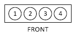
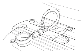
- Attach a compression gauge to the spark plug hole of the No. 1 cylinder.
- Hold the throttle fully open, then crank the engine with the starter motor and count the compression strokes required to reach maximum compression (normally between 6-10).NOTE: If the compression gauge does not hold pressure, check for a missing or damaged Schrader valve in the cylinder side of the compression gauge adaptor hose, or in the gauge pressure bleed off port.
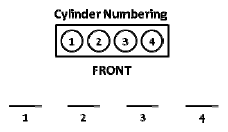
- Record the compression value below, and then measure the compression on the remaining cylinders using the same number of compression strokes. Record their values below, then go to the CYLINDER LEAKAGE TEST .
Minimum Compression Pressure:
135 psi (930 kPa)
Maximum Variation:
29 psi (200kPa)
Variation Example
READING SPECIFICATIONHighest Reading Max Variation Lowest Reading Variation 210 psi 29 psi 170 psi 40 psi
CYLINDER LEAKAGE TEST
- Ensure that the Schrader valve is removed from the cylinder side of the adaptor hose. All of your readings will show 0% leakage if the valve is left in place during testing.
- Disconnect any shop exhaust hoses from the vehicle. The vacuum from these hoses may cause an incorrect diagnosis.
- "K" series L4 engine shown; for other engine types, refer to the appropriate service manual.
- 13. Remove the cylinder head cover.
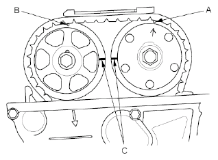
- 14. Set the No. 1 piston at top dead center (TDC). The punch mark (A) on the variable valve timing control (VTC) actuator and the punch mark (B) on the exhaust camshaft sprocket should be at the top. Align the TDC marks (C) on the VTC actuator and the exhaust camshaft sprocket. This procedure only describes DOHC L4 engines.
- 15. Insert the adaptor hose into the No. 1 spark plug hole, and connect the hose to the cylinder leakage tester. Record the cylinder leakage for the No. 1 cylinder. (The cylinder leakage tester must also be connected to shop air.)
Is the leakage greater than 10%?
YES - The cylinder leakage is too high. Listen for escaping air in each of these areas: throttle body (fully open), exhaust pipe, radiator (cap removed), and rocker area. Record the area where the majority of the air is escaping. Go to step 16.
NO - The cylinder leakage is acceptable, go to step 16.
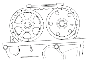
- 16. Rotate the crankshaft 180° clockwise (camshaft pulley turns 90°).
- 17. Insert the adaptor hose into the No. 3 spark plug hole, and connect the hose to the cylinder leakage tester. Record the cylinder leakage for the No. 3 cylinder.
Is the leakage greater than 10%?
YES - The cylinder leakage is too high. Listen for escaping air in each of these areas: throttle body (fully open), exhaust pipe, radiator (cap removed), and rocker area. Record the area where the majority of the air is escaping. Go to step 18.
NO - The cylinder leakage is acceptable, go to step 18.
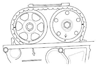
- 18. Rotate the crankshaft 180° clockwise (camshaft pulley turns 90°).
- 19. Insert the adaptor hose into the No. 4 spark plug hole, and connect the hose to the cylinder leakage tester. Record the cylinder leakage for the No. 4 cylinder.
Is the leakage greater than 10%?
YES - The cylinder leakage is too high. Listen for escaping air in each of these areas: throttle body (fully open), exhaust pipe, radiator (cap removed), and rocker area. Record the area where the majority of the air is escaping. Go to step 20.
NO - The cylinder leakage is acceptable, go to step 20.
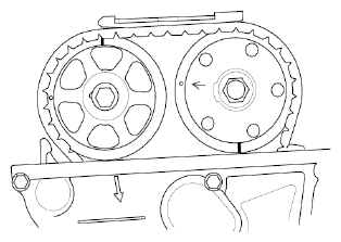
- 20. Rotate the crankshaft 180° clockwise (camshaft pulley turns 90°).
- 21. Insert the adaptor hose into the No. 2 spark plug hole, and connect the hose to the cylinder leakage tester. Record the cylinder leakage for the No. 2 cylinder.
Is the leakage greater than 10%?
YES - The cylinder leakage is too high. Listen for escaping air in each of these areas: throttle body (fully open), exhaust pipe, radiator (cap removed), and rocker area. Record the area where the majority of the air is escaping. Go to step 22.
NO - The cylinder leakage is acceptable, go to step 22.
- 22. Record your test results in a chart similar to the one below.TEST RESULT
Leakage % Leakage Area No. 1 No. 2 No. 3 No. 4 Does any cylinder have leakage greater than 10%?
YES - Go to step 24.
NO - Go to step 23.
- 23. Check your cylinder compression results.
Does the compression vary more than 29 psi between cylinders, or does any cylinder read below 135 psi?
YES - The engine compression is low and cylinder leakage is normal. Check for each of these conditions:
CYLINDER COMPRESSION RESULTLow Compression Inspection Area One cylinder low Worn cam lobes Broken valve springs VCM engines (stuck rocker pins) Bent connecting rod All cylinders read low Worn piston rings Timing belt/chain off a tooth (valve timing) Faulty timing belt/chain tensioner NO - The engine compression and cylinder leakage is normal. Go to step 16.
- 24. Is the majority of the air escaping from the exhaust pipe or throttle body?
YES - Go to step 25.
NO - Go to step 15.
- 25. Check the valve clearances on the problem cylinder(s).
- If the valve clearances are insufficient, adjust as needed, then go to step 26.
- If the valve clearances are OK, go to step 27.
- 26. Recheck the leakage on the cylinders with high leakage.
Is the cylinder leakage within specifications?
YES - Go to step 28.
NO - Go to step 27.
- 27. Compare your test results to the chart below, and inspect/repair the associated components as needed.TEST RESULT
Leakage Area Inspection Area Rocker, oil cap, dipstick tube, breather tube Piston rings Cylinder walls Throttle body Intake valves Exhaust pipe Exhaust valves Radiator (bubbles in coolant) Head gasket Engine block Cylinder head - 28. Remove the cylinder leak-down gauge from the spark plug hole.
- 29. Reinstall the cylinder head cover.
- 30. Reinstall the spark plugs.
- 31. Reinstall the ignition coils.