Key Interlock System Circuit Troubleshooting
NOTE:
- SRS components are located in this area. Review the SRS component locations , and precautions and procedures before doing repairs or servicing.
- Refer to the Electrical Wiring Diagrams for the location of the under-dash fuse/relay box connectors.
- 1. DTC check:
- 1. Check the CVT system DTCs with the HDS.
DTC Description Confirmed DTC Pending DTC Freeze Frame DTCs (CVT system)
Are DTCs indicated?
YES
Go to the CVT system DTC troubleshooting - Refer to: CVT System DTC Troubleshooting Index (Except Touring)Fuel and Emissions Systems DTC Troubleshooting Index (Except Touring) .
NO
Go to step 2.
- 2. Key interlock system check:
- 1. Check the parameter(s) below with the HDS.
Signal Current conditions Values Unit Park Pin Switch Is the transmission range switch indicated ON when the shift lever is in P, and does the transmission range switch indicate OFF when the shift lever is shifted to any position other than P?
YES
Go to step 3.
NO
Go to step 10.
- 3. Determine possible failure area (steering lock, others):
- 1. Move the shift lever to P and set the parking brake.
- 2. Remove the steering column covers.
- 3. Disconnect the following connector.
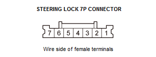
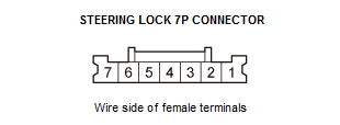
Steering lock 7P connector - 4. Turn the vehicle to ACCESSORY mode.
- 5. Check if the ignition switch can be turned to OFF (LOCK) mode.
Can the ignition switch be turned to OFF (LOCK) mode?
YES
Go to step 4.
NO
Faulty key interlock solenoid; replace the steering lock .
- 4. Fuse check:
- 1. Check the following fuse.
Fuse No. B20 (7.5 A) Location Under-dash fuse/relay box Is the fuse OK?
YES
Go to step 5.
NO
Replace the fuse. If the fuse blows again, repair a short to ground in the No. B20 (7.5 A) fuse circuit.
- 5. Shorted wire check (KEY SOL line):
- 1. Make sure the vehicle is turned to the OFF (LOCK) mode.
- 2. Disconnect the following connector.
Under-dash fuse/relay box connector P (20P) - 3. Check for continuity between test points 1 and 2.
Test condition Vehicle OFF (LOCK) mode Steering lock 7P connector: disconnected Under-dash fuse/relay box connector P (20P): disconnected Test point 1 Steering lock 7P connector No. 4 Test point 2 Body ground Is there continuity?
YES
Repair a short to body ground in the wire.
NO
The KEY SOL wire is not shorted to ground. Go to step 6.
- 6. Open wire check (KEY SOL line):
- 1. Check for continuity between test points 1 and 2.
Test condition Vehicle OFF (LOCK) mode Steering lock 7P connector: disconnected Under-dash fuse/relay box connector P (20P): disconnected Test point 1 Under-dash fuse/relay box connector P (20P) No. 10 Test point 2 Steering lock 7P connector No. 4 Is there continuity?
YES
The KEY SOL wire is OK. Go to step 7.
NO
Repair an open or high resistance in the wire.
- 7. Park pin switch check:
- 1. Remove the center console.
- 2. Disconnect the following connectors.
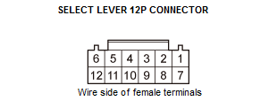
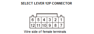
Select lever 12P connector - 3. Do the park pin switch test .
Is switch OK?
YES
Go to step 8.
NO
- 8. Shorted wire check (P-PIN SW line):
- 1. Check for continuity between test points 1 and 2.
Test condition Vehicle OFF (LOCK) mode Steering lock 7P connector: disconnected Under-dash fuse/relay box connector P (20P): disconnected Select lever 12P connector: disconnected Test point 1 Select lever 12P connector No. 6 Test point 2 Body ground Is there continuity?
YES
Repair a short to body ground in the wire.
NO
The P-PIN SW wire is OK. Go to step 9.
- 9. Open wire check (GND line):
- 1. Check for continuity between test points 1 and 2.
Test condition Vehicle OFF (LOCK) mode Steering lock 7P connector: disconnected Under-dash fuse/relay box connector P (20P): disconnected Select lever 12P connector: disconnected Test point 1 Select lever 12P connector No. 5 Test point 2 Body ground Is there continuity?
YES
The GND wire is OK. Go to step 10.
NO
Repair an open or high resistance in the ground wire or poor ground (G502).
- 10.Transmission range switch check:
- 1. Do the transmission range switch test .
Is switch OK?
YES
Go to step 11.
NO
- 11.Open wire check (ATP-P line):
- 1. Disconnect the following connectors.
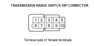
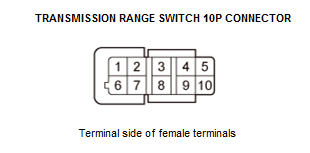
Under-dash fuse/relay box connector D (32P) Transmission range switch 10P connector - 2. Check for continuity between test points 1 and 2.
Test condition Vehicle OFF (LOCK) mode Steering lock 7P connector: disconnected Under-dash fuse/relay box connector P (20P): disconnected Select lever 12P connector: disconnected Under-dash fuse/relay box connector D (32P): disconnected Transmission range switch 10P connector: disconnected Test point 1 Under-dash fuse/relay box connector D (32P) No. 22 Test point 2 Transmission range switch 10P connector No. 5 Is there continuity?
YES
The ATP-P wire is OK. Go to step 12.
NO
Repair an open or high resistance in the wire.
- 12.Open wire check (GND line):
- 1. Check for continuity between test points 1 and 2.
Test condition Vehicle OFF (LOCK) mode Steering lock 7P connector: disconnected Under-dash fuse/relay box connector P (20P): disconnected Select lever 12P connector: disconnected Under-dash fuse/relay box connector D (32P): disconnected Transmission range switch 10P connector: disconnected Test point 1 Transmission range switch 10P connector No. 1 Test point 2 Body ground Is there continuity?
YES
The GND wire is OK. Faulty MICU, replace the under-dash fuse/relay box .
NO
Repair an open or high resistance in the ground wire or poor ground (G101).