Engine will not start, engine starts but stalls immediately, or engine is hard to start
Special Tools Required
Vacuum Pump/Gauge, 0-30 inHg Snap-on YA4000A or equivalent, commercially available
NOTE:
- Before beginning this troubleshooting, do a customer diagnostic interview - Refer to: Fuel and Emissions Systems Symptom Troubleshooting - Hard to start engine - Diagnostic interview Fuel and Emissions Systems Symptom Troubleshooting - Engine stalls - Diagnostic interview .
-
- When the symptom cannot be duplicated, you can do the troubleshooting using the on-board snapshot information in this procedure - Refer to: PGM-FI System Description - OBD PGM-FI System Description - On-Board Snapshot . Refer to the diagnostic interview (date, place) and the present total mileage, and compare the total mileage which is estimated from the interview when a failure occurred and the parameter (total mileage) in the on-board snapshot information. Make sure the date when the failure occurred corresponds with the date on which the on-board snapshot information was recorded. If it doesn't, the on-board snapshot information cannot be used in this troubleshooting.
- Before beginning this troubleshooting:
-
- Make sure the 12 volt battery is fully charged.
- Make sure the fuel tank is at least 1/4 full.
- Make sure the engine oil level is correct.
- After the troubleshooting, reset the PCM with the HDS to erase the on-board snapshot information recorded on the PCM.
- 1. DTC check:
- 1. Turn the vehicle to the ON mode.
- 2. Check for Pending or Confirmed DTCs with the HDS.
DTC Description Confirmed DTC Pending DTC Freeze Frame Are any Pending or Confirmed DTCs indicated?
YES
Go to the indicated DTC's troubleshooting.
NO
Go to step 2.
NOTE: If the HDS does not communicate with the vehicle, go to the PCM power and ground circuit troubleshooting .
- 2. Immobilizer system check:
- 1. Check the immobilizer status log (With keyless access system) , (Without keyless access system) .
NOTE: When a status log count is found, it means the immobilizer system has kept the engine from starting in the past. The number of status log count shows how often the system has kept the engine from starting in the past. If the immobilizer system has no status log count, the system is normal.
Were any status log counts found?
YES
Check for probable cause of the status log.
NO
Go to step 3.
- 3. Problem verification (snapshot sampling):
- 1. Set the HDS to record a HIGH-SPEED SNAPSHOT of following parameters for 30 seconds.
- IMMOBILIZER
- ENGINE SPEED
- BATTERY
- ECT SENSOR 1
- MAP SENSOR
- MAF SENSOR
- FUEL PRESSURE CONVERTED FROM PF SENSOR
- FUEL PRESSURE DIRECT INJECTION SYSTEM
- CMP B NO PULSE
- CMP B NOISE
- CKP NO PULSE
- CKP NOISE
- VTEC PRES SW (USA and Canada models)
Data List
- 2. Begin the snapshot, then try to start the engine.
Is the engine hard to start?
YES
Go to step 6 (diagnosis by parameter troubleshooting).
NO
Go to step 4.
- 4. On-board snapshot check (Engine will not start):
- 1. Check the record of Hard to Start Engine in the on-board snapshot with the HDS.
On-board Snapshot
Is the Hard to Start Engine in the on-board snapshot recorded?
YES
Go to step 6 (diagnosis by parameter troubleshooting).
NO
Go to step 5.
- 5. On-board snapshot check (Engine Stall 2):
NOTE: If a Hard to Start on-board snapshot data was not recorded, use the Engine Stall 2 on-board snapshot data and check the cause of the failure.
- 1. Check for a record of Engine Stall 2 in the on-board snapshot with the HDS.
On-board Snapshot
Is an Engine Stall 2 on-board snapshot recorded?
YES
Go to step 20 (diagnosis by parameter AF FB (ST FUEL TRIM)).
NO
Go to step 22 (fuel system troubleshooting).
NOTE: In case of the following conditions, the on-board snapshot cannot be recorded when the engine stalls.
- The vehicle is turned to the OFF (LOCK) mode after starting the engine.
- Vehicle condition not in the on-board snapshot recording zone of Hard to start engine - Refer to: PGM-FI System Description - OBD PGM-FI System Description - On-Board Snapshot .
- Low or dead 12 volt battery
- Replacing the 12 volt battery
- 6. On-board snapshot or snapshot check (IMMOBILIZER):
NOTE: Use the on-board snapshot in the case of an intermittent failure, or use the snapshot in the case of a reproducible failure.
- 1. Select the Hard to Start Engine in the on-board snapshot or snapshot with the HDS.
On-board Snapshot
- 2. Select the IMMOBILIZER and ENGINE SPEED in the configuration list.
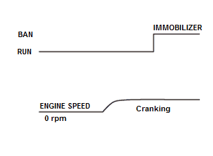
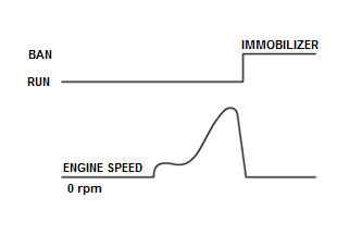
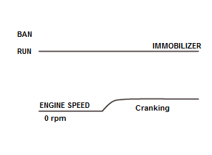
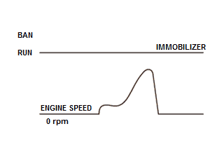
Compare the snapshot parameters observed while the engine was cranking, to those in the chart below, to determine the problem.
Pattern Symptom (Diagnosis by parameter) Additional remarks Pattern 1 IMMOBILIZER inhibit IMMOBILIZER inhibit
When IMMOBILIZER indicates "BAN" during cranking or after start, the fuel pump is stopped by IMMOBILIZER inhibit. - No failure in the engine
Pattern Symptom (Diagnosis by parameter) Additional remarks Pattern 2 IMMOBILIZER permit Normal IMMOBILIZER permit Normal
IMMOBILIZER is normal when IMMOBILIZER indicates "RUN" when cranking or after start. Which pattern is indicated?
Pattern 1
The immobilizer system has a failure. Go to the immobilizer System Check (With keyless access system) , (Without keyless access system) .
Pattern 2
The immobilizer system is OK. Go to step 7 (diagnosis by parameter (ENGINE SPEED)).
- 7. On-board snapshot or snapshot check (ENGINE SPEED):
NOTE: Use the on-board snapshot in the case of an intermittent failure, or use the snapshot in the case of a reproducible failure.
- 1. Select the Hard to Start Engine in the on-board snapshot or snapshot with the HDS.
On-board Snapshot
- 2. Select the ENGINE SPEED pattern chart in the configuration list.
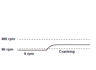
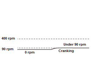
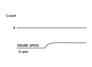
Check the recorded snapshot parameters while the engine is cranking, then compare the pattern from the chart, and determine the problem.
Pattern Symptom (Diagnosis by parameter) Additional remarks Pattern 1 ENGINE SPEED when cranking is normal Pattern 2 ENGINE SPEED when cranking is low When ENGINE SPEED during cranking is low, weak 12 volt battery or increased engine friction can be considered. Which pattern is indicated?
Pattern 1
The engine cranking speed is OK. Go to step 8 (diagnosis by parameter (BATTERY)).
Pattern 2
Diagnostic procedure:
- 1.
- 2.
Check the 12 volt battery cables and the connections.
- 3.
- 4.
Check for engine friction.
- 8. On-board snapshot or snapshot check (BATTERY):
NOTE: Use the on-board snapshot in the case of an intermittent failure, or use the snapshot in the case of a reproducible failure.
- 1. Select the Hard to Start Engine in the on-board snapshot or snapshot with the HDS.
On-board Snapshot
- 2. Select the BATTERY and ENGINE SPEED in the configuration list.
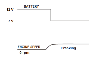
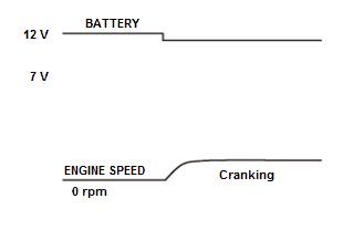
Check the recorded snapshot parameters while the engine is cranking, then compare the BATTERY pattern from the chart, and determine the problem.
Pattern Symptom (Diagnosis by parameter) Additional remarks Pattern 1 BATTERY voltage low when cranking - When BATTERY voltage during cranking is too low, there is a possibility that PCM and/or engine will not start.
- The PCM and other system control units require 7.0 V or more to start.
Pattern 2 BATTERY voltage normal when cranking To start the engine, 7.0 V or more is needed Which pattern is indicated?
Pattern 1
Diagnostic procedure:
- 1.
- 2.
Check the 12 volt battery cables and the connections.
Pattern 2
The 12 volt battery is OK. Go to step 9 (diagnosis by parameter (ECT SENSOR 1)).
- 9. On-board snapshot or snapshot check (ECT SENSOR 1):
NOTE: Use the on-board snapshot in the case of an intermittent failure, or use the snapshot in the case of a reproducible failure.
- 1. Select the Hard to Start Engine in the on-board snapshot or snapshot with the HDS.
On-board Snapshot
- 2. Select the ECT SENSOR 1 and ENGINE SPEED in the configuration list.
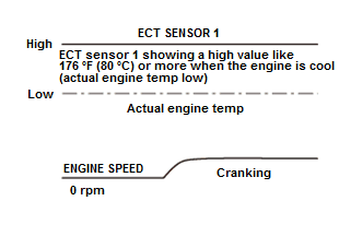
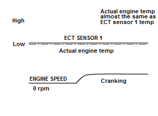
Check the recorded snapshot parameters while the engine is cranking, then compare the ECT SENSOR 1 pattern from the chart, and determine the problem.
Pattern Symptom (Diagnosis by parameter) Additional remarks Pattern 1 ECT SENSOR 1 high when cranking When ECT SENSOR 1 indicates about 176 °F (80 °C) or more when the engine is cold (engine temp low), ECT sensor 1 may be stuck high. ECT compensation is not applied after the engine is warmed up, it is not necessary to check ECT sensor 1 (not a faulty part). Pattern 2 ECT SENSOR 1 normal when cranking If actual engine temp is nearly the same as the temp indicated by ECT sensor 1 when cranking, ECT sensor 1 is normal. Which pattern is indicated?
Pattern 1
Check for a short in the ECT sensor 1 circuit and a failure in ECT sensor 1.
Pattern 2
Go to step 10.
- 10.ECT sensor 1 check:
- 1. Turn the vehicle to the OFF (LOCK) mode.
- 2. Let the engine cool for 24 hours.
- 3. Measure the ambient temperature of the engine with the thermometer.
- 4. Turn the vehicle to the ON mode, but do not start the engine.
- 5. Check the parameter(s) below with the HDS.
Signal Current conditions Values Unit ECT SENSOR 1 ECT SENSOR 2 Are the values of ECT SENSOR 1, ECT SENSOR 2, and the ambient temperature almost the same?
YES
ECT sensor 1 is OK. Go to step 11 (diagnosis by parameter (MAP SENSOR)).
NO
If the value of ECT SENSOR 1 is much higher (or lower) than that of ECT SENSOR 2, and the ambient temperature, check for the ECT sensor 1 circuit and a failure in ECT sensor 1.
- 11.On-board snapshot or snapshot check (MAP SENSOR):
NOTE: Use the on-board snapshot in the case of an intermittent failure, or use the snapshot in the case of a reproducible failure.
- 1. Select the Hard to Start Engine in the on-board snapshot or snapshot with the HDS.
On-board Snapshot
- 2. Select the MAP SENSOR and ENGINE SPEED in the configuration list.
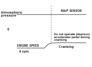
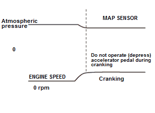
Check the recorded snapshot parameters while the engine is cranking, then compare the MAP SENSOR pattern to the pattern from the chart below, and determine the problem.
Pattern Symptom (Diagnosis by parameter) Additional remarks Pattern 1 MAP SENSOR detects no change of pressure when cranking When MAP SENSOR detects no change of pressure when cranking, the pressure measurement port may be clogged. The PCM decides basic duration time of fuel injection from engine speed and MAP sensor signal when cranking. Pattern 2 Normal when MAP SENSOR detects vacuum when cranking When MAP SENSOR detects vacuum while cranking, the condition is normal and the MAP sensor pressure port is clear. Which pattern is indicated?
Pattern 1
Check the pressure measurement port of the MAP sensor for clogging, foreign objects, etc.
Pattern 2
The MAP sensor is OK. Go to step 12 (diagnosis by parameter (MAF SENSOR)).
- 12.On- board snapshot or snapshot check (MAF SENSOR):
NOTE: Use the on-board snapshot in the case of an intermittent failure, or use the snapshot in the case of a reproducible failure.
- 1. Select the Hard to Start Engine in the on-board snapshot or the snapshot with the HDS.
On-board Snapshot
- 2. Select the MAF SENSOR and ENGINE SPEED in the configuration list.
Check the recorded snapshot parameters while the engine is cranking, then compare the MAF SENSOR pattern from the chart, and determine the problem.
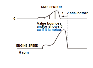
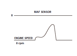
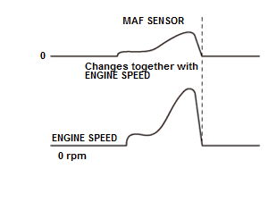
Pattern Symptom (Diagnosis by parameter) Additional remarks Pattern 1 Poor connection of MAF SENSOR Complete combustion stall: When MAF SENSOR indicates "0" 1-2 sec. before ENGINE SPEED becomes 0 rpm, or when "0" is shown like noise, there may be a poor connection at the MAF sensor connector. Pattern 2 MAF SENSOR output incorrect When MAF SENSOR shows "0" when cranking or after start, clogging in MAF sensor's measurement port may be contaminated with debris or there may be a poor connection as its connector. Pattern Symptom (Diagnosis by parameter) Additional remarks Pattern 3 MAF SENSOR Normal When MAF SENSOR output compares with ENGINE SPEED when cranking or after starting, the MAF sensor is normal. Which pattern is indicated?
Pattern 1 and 2
Check for loose terminals or a poor connection at the MAF sensor/IAT sensor.
Pattern 3
The MAF sensor/IAT sensor is OK. Go to step 13 (diagnosis by parameter (FUEL PRESSURE CONVERTED FROM PF SENSOR and FUEL PRESSURE DIRECT INJECTION SYSTEM)).
- 13.On-board snapshot or snapshot check (FUEL PRESSURE CONVERTED FROM PF SENSOR and FUEL PRESSURE DIRECT INJECTION SYSTEM):
NOTE: Use the on-board snapshot in the case of an intermittent failure, or use the snapshot in the case of a reproducible failure.
- 1. Select the Hard to Start Engine in the on-board snapshot or snapshot with the HDS.
On-board Snapshot
- 2. Select the FUEL PRESSURE CONVERTED FROM PF SENSOR, the FUEL PRESSURE DIRECT INJECTION SYSTEM, and ENGINE SPEED in the configuration list.
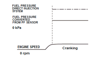
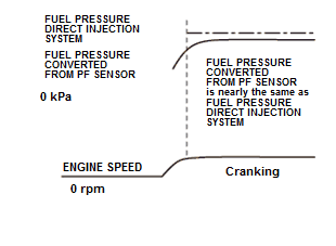
Check the recorded snapshot or on-board snapshot parameters while the engine is cranking, then compare the FUEL PRESSURE CONVERTED FROM PF SENSOR and FUEL PRESSURE DIRECT INJECTION SYSTEM patterns from the chart, and determine the problem.
Pattern Symptom (Diagnosis by parameter) Additional remarks Pattern 1 The FUEL PRESSURE CONVERTED FROM PF SENSOR is low (almost 0 kPa) when cranking If the FUEL PRESSURE CONVERTED FROM PF SENSOR is almost 0 kPa when cranking, a failure may exist in the fuel supply system. - Fuel leak, out of fuel
- Fuel rail pressure sensor failure
- Spill valve stuck off
- Fuel pressure regulator (low pressure side)
- Fuel pump (low pressure side)
- High pressure fuel pump
Pattern 2 Normal when the FUEL PRESSURE CONVERTED FROM PF SENSOR follows the FUEL PRESSURE DIRECT INJECTION SYSTEM when cranking If the FUEL PRESSURE CONVERTED FROM PF SENSOR is nearly the same as the FUEL PRESSURE DIRECT INJECTION SYSTEM when cranking, the fuel pressure is normal. Fuel pressure may be low when the start of cranking.
Which pattern is indicated?
Pattern 1
Go to the troubleshooting for DTC P0087 .
Pattern 2
The fuel pressure is OK. Go to step 14 (diagnosis by parameter (CMP B NO PULSE)).
- 14.On-board snapshot or snapshot check (CMP B NO PULSE):
NOTE: Use the on-board snapshot in the case of an intermittent failure, or use the snapshot in the case of a reproducible failure.
- 1. Select the Hard to Start Engine in the on-board snapshot or snapshot with the HDS.
On-board Snapshot
- 2. Select the CMP B NO PULSE and ENGINE SPEED in the configuration list.
Check the recorded snapshot parameters while the engine is cranking, then compare the CMP B NO PULSE pattern from the chart, and determine the problem.
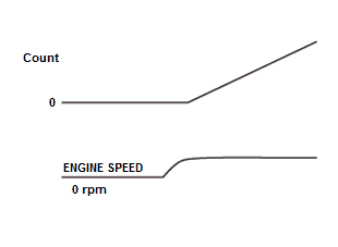
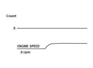
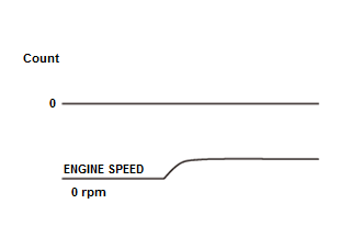
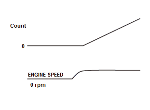
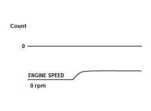
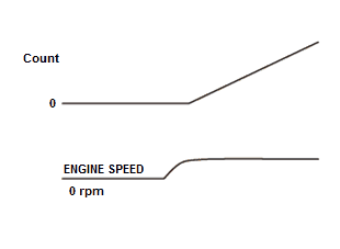
Pattern Symptom (Diagnosis by parameter) Additional remarks Pattern 1 CMP B NO PULSE count increases when cranking When CMP B NO PULSE count increase when cranking, no CMP pulse is received. If the CMP pulse is not received, the PCM cannot detect the cylinder to be ignited and the engine is unable to start. Pattern 2 The CMP B NO PULSE indicates the pulse is normal It is normal when CMP B NO PULSE count does not increase. Which pattern is indicated?
Pattern 1
Go to the troubleshooting for DTC P0365 . If the CMP B NO PULSE count reaches the malfunction threshold, DTC P0365 will set. Check for poor connections and loose terminals at CMP sensor B.
Pattern 2
Go to step 15 (diagnosis by parameter (CMP B NOISE)).
- 15.On-board snapshot or snapshot check (CMP B NOISE):
NOTE: Use the on-board snapshot in the case of an intermittent failure, or use the snapshot in the case of a reproducible failure.
- 1. Select the Hard to Start Engine in the on-board snapshot or snapshot with the HDS.
On-board Snapshot
- 2. Select the CMP B NOISE and ENGINE SPEED in the configuration list.
Check the recorded snapshot parameters while the engine is cranking, then compare the CMP B NOISE pattern from the chart, and determine the problem.
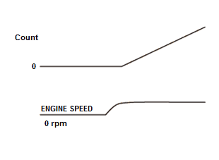
Pattern Symptom (Diagnosis by parameter) Additional remarks Pattern 1 CMP B NOISE count increases when cranking When CMP B NOISE count increases when cranking, there is noise in the CMP signal. When CMP signal has noise, the PCM cannot detect the cylinder to be ignited and the engine is unable to start. Pattern 2 The CMP B NOISE indicates the pulse is normal It is normal when CMP B NOISE count does not increase when cranking. Which pattern is indicated?
Pattern 1
Go to the troubleshooting for DTC P0369 . If the CMP B NOISE count reaches the malfunction threshold, DTC P0369 will set. Check for poor connections and loose terminals at CMP sensor B.
Pattern 2
CMP sensor B is OK. Go to step 16 (diagnosis by parameter (CKP NO PULSE)).
- 16.On-board snapshot or snapshot check (CKP NO PULSE):
NOTE: Use the on-board snapshot in the case of an intermittent failure, or use the snapshot in the case of a reproducible failure.
- 1. Select the Hard to Start Engine in the on-board snapshot or snapshot with the HDS.
On-board Snapshot
- 2. Select the CKP NO PULSE and ENGINE SPEED in the configuration list.
Check the recorded snapshot parameters while the engine is cranking, then compare the CKP NO PULSE pattern from the chart, and determine the problem.
Pattern Symptom (Diagnosis by parameter) Additional remarks Pattern 1 CKP NO PULSE counts go up when cranking When the CKP NO PULSE count increases when cranking, the PCM is not receiving the correct CKP pulse. Pattern 2 The CKP NO PULSE indicates the pulse is normal It is normal when the CKP NO PULSE count does not increase. Which pattern is indicated?
Pattern 1
Go to the troubleshooting for DTC P0335 . If the CKP NO PULSE count reaches the malfunction threshold, DTC P0335 will set. Check for poor connections and loose terminals at the CKP sensor.
Pattern 2
Go to step 17 (diagnosis by parameter (CKP NOISE)).
- 17.On-board snapshot or snapshot check (CKP NOISE):
NOTE: Use the on-board snapshot in the case of an intermittent failure, or use the snapshot in the case of a reproducible failure.
- 1. Select the Hard to Start Engine in the on-board snapshot or snapshot with the HDS.
On-board Snapshot
- 2. Select the CKP NOISE and ENGINE SPEED in the configuration list.
Check the recorded snapshot parameters while the engine is cranking, then compare the CKP NOISE pattern from the chart, and determine the problem.
Pattern Symptom (Diagnosis by parameter) Additional remarks Pattern 1 CKP NOISE count goes up when cranking When the CKP NOISE count increases when cranking, the PCM is not receiving the correct CKP pulse. Pattern 2 Normal when CKP NOISE count does not go up when cranking It is normal when CKP NOISE count does not increase when cranking. Which pattern is indicated?
Pattern 1
Go to the troubleshooting for DTC P0339 . If the CKP NOISE count reaches the malfunction threshold, DTC P0339 will set. Check for poor connections and loose terminals at the CKP sensor, and also check for aftermarket accessories.
Pattern 2 (Reproducible failure: USA and Canada models)
The CKP sensor is OK. Go to step 18 (diagnosis by parameter (VTEC PRES SW)).
Pattern 2 (Reproducible failure: Mexico models)
The CKP sensor is OK. Go to step 22 (fuel system troubleshooting).
Pattern 2 (Intermittent failure)
The CKP sensor is OK. Go to step 19 (diagnosis by parameter (Engine Stall 2 in the on-board snapshot)).
- 18.Snapshot check (VTEC PRES SW):
- 1. Check the parameter(s) below with the HDS while engine cranking.
Signal Threshold Current conditions Values Unit Values Unit VTEC PRES SW OFF Do the current condition(s) match the threshold?
YES
Substitute a known-good rocker arm oil control valve . If the valve is OK, replace the oil pump .
NO
The rocker arm oil pressure switch is OK. Go to step 22 (fuel system troubleshooting).
- 19.On-board snapshot check (Engine Stall 2):
- 1. Check for a record of Engine Stall 2 in the on-board snapshot with the HDS.
On-board Snapshot
Is an Engine Stall 2 on-board snapshot recorded?
YES
Go to step 20 (diagnosis by parameter AF FB (ST FUEL TRIM)).
NO
Go to step 22 (fuel system troubleshooting).
- 20.On-board snapshot check AF FB (ST FUEL TRIM):
- 1. Check for a record of Engine Stall 2 in the on-board snapshot with the HDS.
On-board Snapshot
- 2. Select the AF FB (ST FUEL TRIM) and ENGINE SPEED in the configuration list.
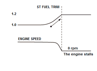
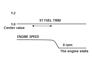
Check the recorded snapshot parameters at the time of the engine stalls, then compare the AF FB (ST FUEL TRIM) pattern from the chart, and determine the problem.
Pattern Symptom (Diagnosis by parameter) Additional remarks Pattern 1 Engine stalls while AF FB (ST FUEL TRIM) value is increasing If the engine stalls while AF FB (ST FUEL TRIM) value is increasing, a failure may exist in the fuel system. Pattern Symptom (Diagnosis by parameter) Additional remarks Pattern 2 Normal when the engine stalls when AF FB (ST FUEL TRIM) is around 1.0 (center value) The fuel is normal when the engine stalls with AF FB (ST FUEL TRIM) around 1.0 (center value). Which pattern is indicated?
-
Pattern 1
Diagnostic procedure:
- 1.
Check the fuel pump operation sound.
- 2.
- 3.
- 4.
- 5.
- 6.
Check for the following fuses:
-
- No. A23 (15 A) fuse (in the under-hood fuse/relay box)
- No. B4 (15 A) fuse (in the under-dash fuse/relay box)
Pattern 2
Go to step 21 (diagnosis by parameter (MISFIRE)).
- 1.
-
- 21.On-board snapshot check (MISFIRE):
- 1. Check for a record of Engine Stall 2 in the on-board snapshot with the HDS.
On-board Snapshot
- 2. Select the MISFIRE and ENGINE SPEED in the configuration list.
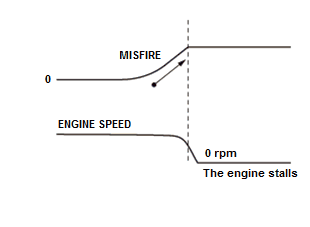
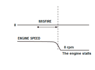
Check the recorded snapshot parameters at the time of the engine stalls, then compare those snapshots to the MISFIRE pattern from the chart, and determine the problem.
Pattern Symptom (Diagnosis by parameter) Additional remarks Pattern 1 Engine stalls after MISFIRE counts increase If the engine stalls after MISFIRE count increases, the engine stall may be caused by misfire. Also the misfire may be caused by a loss of compression, faulty ignition system, faulty fuel system, etc. Pattern 2 Normal when engine stalls with MISFIRE count remaining constant If the MISFIRE count remains steady when the engine stalls, the stall was not caused by a misfire. Which pattern is indicated?
Pattern 1
Diagnostic procedure:
- 1.
If misfire counts go up without storing misfire DTC P0300-P0304, go to the troubleshooting for DTC P0300-P0304 .
- 2.
If the misfire count reaches the malfunction threshold, DTC P0300-P0304 is stored. Go to the troubleshooting for DTC P0300-P0304 .
Pattern 2
Go to step 22 (fuel system troubleshooting).
- 1.
- 22.Fuel pressure check (low pressure side):
- 1. Do the fuel pressure test .
Is the fuel pressure OK?
YES
Go to step 23.
NO
Check the following parts:
- 23.Spark plug visual check:
- 1. Turn the vehicle to the OFF (LOCK) mode.
- 2. Remove the spark plugs .
- 3. Check the condition of the spark plug electrodes.
NOTE: Make sure the spark plugs are the correct part number for the vehicle. If the plugs are aftermarket or they are not the correct part number, replace all of the plugs and retest.
Is the electrode damage or wet?
-
YES (wet)
Check the following conditions. If those conditions do not apply, go to step 24.
- In very cold conditions, multiple very short trips can cause the spark plug to foul. If this is the case, drive the vehicle a longer distance and recheck.
- Incorrect or poor quality fuel can cause a wet spark plug. Replace the fuel and recheck.
YES (damaged)
Replace the damaged spark plugs , determine the cause of the spark plug damage.
NO
Go to step 24.
-
- 24.Determine possible failure area (ignition system, others):
- 1. Turn the vehicle to the OFF (LOCK) mode.
- 2. Fit a spark plug to the ignition coil and ground it to the engine.
- 3. Turn the vehicle to the ON mode.
- 4. Select ALL INJECTORS STOP in the INSPECTION MENU with the HDS, and stop fuel injection from the injector.
ALL INJECTORS STOP
- 5. Crank the engine and watch for spark at the spark plug.
Does the spark plug spark?
YES
The ignition system is OK. Select PCM reset in the PGM-FI INSPECTION MENU to cancel ALL INJECTORS STOP with the HDS, then go to step 26 (engine compression troubleshooting).
NO
Go to step 25.
- 25.Ignition coil power circuit check:
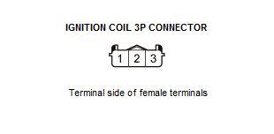
- 1. Disconnect the following connectors.
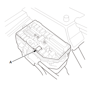
Ignition coil(s) 3P connector from the problem cylinder - 2. Remove the ignition coil relay (A) from the under-hood fuse/relay box.
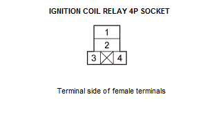
- 3. Check for continuity between test points 1 and 2.
Test condition Vehicle OFF (LOCK) mode Ignition coil 3P connector: disconnected Ignition coil relay: disconnected Test point 1 Ignition coil relay 4P socket No. 2 Test point 2 Ignition coil 3P connector No. 1 Is there continuity?
YES
The ignition coil power circuit is OK. Replace the ignition coil(s) .
NO
Repair an open in the IG1(IGN COIL)/IG1(COIL)/IG COIL RLY OUT wire between the ignition coil relay and the ignition coil.
- 26.Engine compression check:
- 1. Do an engine compression inspection.
Is engine compression OK?
YES
Go to step 27 (EVAP canister purge valve check).
NO
Check for wear or damage to these parts:
- Incorrect valve clearance
- Confirmation of cam timing
- Oil pressure relief valve
- Damage or worn cam lobes
- Damage or worn valve and seats
- Damage cylinder head gasket
- Damage or worn piston rings
- Damage or worn piston and cylinder bore
- 27.EVAP canister purge valve check:
- 1. Turn the vehicle to the OFF (LOCK) mode.
- 2. Remove the high pressure fuel pump cover and the fuel bracket .
- 3. Disconnect the following connector.
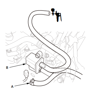
EVAP canister purge valve 2P connector - 4. Disconnect the vacuum hose (A) from the EVAP canister purge valve (B) in the engine compartment, and connect a vacuum pump/gauge, 0-30 inHg, to the purge valve.
- 5. Start the engine.
Does the vacuum pump indicate vacuum?
YES
Replace the EVAP canister purge valve .
NO (Reproducible failure)
Go to step 28 (fuse check).
NO (Intermittent failure)
Go to step 29 (relay check).
- 28.Fuse check:
- 1. Check the following fuses.
Fuse No. A12 (20 A) to the injector relay No. A17 (15 A) to the ignition coil relay No. A18 (15 A) to the PGM-FI subrelay No. A23 (15 A) to PGM-FI main relay 1 Location Under-hood fuse/relay box Fuse No. B4 (15 A) to PGM-FI main relay 2 Location Under-dash fuse/relay box Are the fuses OK?
YES
The fuses are OK. Go to step 29 (relay check).
NO
Replace the blown fuse(s).
- 29.Relay check:
- 1. Test the following relays:
NOTE: In case the failure is not reproduced, the following relays may have an intermittent failure.
Are the relays OK?
YES
Go to step 30 (power and ground terminal check).
NO
Replace any damaged relays.
- 30.Power and ground terminal check:
- 1. Check the corrosion and looseness at the following terminals:
- 12 volt battery terminals
- Ground cable terminals between the engine and the body ground, and the transmission and the body ground
- Engine wire harness ground (G101, G102)
Are the terminals OK?
YES
Go to step 31 (connector terminal check).
NO
Repair any terminal(s) as needed.
- 31.Connector terminal check:
- 1. Check the foreign objects clogged and corrosion at the following connector terminals:
- PCM connectors
-
- IG1 FI-ECU, FI MAIN RLY CL-
- VBDBW, DBW RLY CL-
- IG1 (F/P), FUEL PUMP RLY CL-
- INJ RLY OUT, INJ RLY CL-
- GND1, GND2, GND3, PGM (GND), GND INJ1, GND INJ2
- INJ H1, INJ L1, INJ H2, INJ L2, INJ H3, INJ L3, INJ H4, INJ L4
- IGN01, IGN02, IGN03, IGN04
- HPUMP H, HPUMP L
- CAM
- TDC
- CRKN
- PB
- VGP, VGM
- TW
- PCS
- MTR1, MTR2, THL1, THL2
- CMP sensor A
- CMP sensor B
- CKP sensor
- Ignition coils
- Injectors
- High pressure fuel pump
- ECT sensor
- MAF sensor
- MAP sensor
- Throttle body
- EVAP canister purge valve
- Fuel tank unit
Are the terminals OK?
YES
Go to the diagnostic interview for hard to start engine - Refer to: Fuel and Emissions Systems Symptom Troubleshooting - Hard to start engine - Diagnostic interview Fuel and Emissions Systems Symptom Troubleshooting - Engine stalls - Diagnostic interview .
NO
Repair any terminal(s) as needed.