CVT Transmission Disassembly and Reassembly: Disassembly
NOTE:
- Refer to the Exploded View as needed during this procedure.
- Keep all foreign particles out of the transmission.
- Unless otherwise indicated, illustrations used in the procedure are for AWD/4WD.
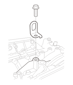
- 1. Transmission Hanger - Remove
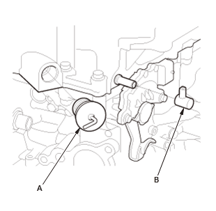
- 2. Transmission Fluid Filler Cap and Breather Cap - Remove
1. Remove the transmission fluid filler cap (A) and the breather cap (B).
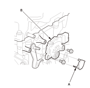
- 3. Transmission Range Switch - Remove
1. Remove the control shaft cover (A)
2. Remove the transmission range switch (B).
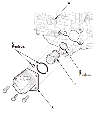
- 4. Transmission Fluid Warmer and Transmission Fluid Warmer Strainer - Remove
NOTE: To prevent damage, cover the connector (A) using a shop towel.
1. Remove the transmission fluid warmer (B) with the O-rings (C).
NOTE: The transmission fluid warmer is aluminum part. Be careful not to damage the transmission fluid warmer
2. Remove the transmission fluid warmer strainer (D) with the O-ring (E)
3. Check the transmission fluid warmer strainer for damage or clogging. If it is damaged or clogged, replace it.
NOTE:
- Do not use compressed air to clean the transmission fluid warmer strainer.
- Soak the transmission fluid warmer strainer thoroughly in transmission fluid.
- 5. CVT Drive Pulley Speed Sensor, Torque Converter Turbine Speed Sensor, and CVT Driven Pulley Pressure Sensor - Remove
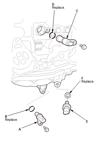
1. Remove the CVT drive pulley speed sensor (A) with the O-ring (B)
2. Remove the torque converter turbine speed sensor (C) with the O-ring (D)
3. Remove the CVT driven pulley pressure sensor (E) with the sealing washer (F).
NOTE: Be careful not to damage the plastic part.
- 6. CVT Speed Sensor - Remove
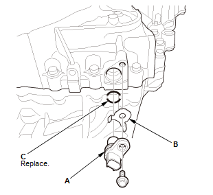
1. Remove the CVT speed sensor (A) and the sensor washer (B) with the O-ring (C).
- 7. Transmission - Turn Transmission Upside Down
1. Turn the transmission upside down, and set it on the workbench to prevent damaging the input shaft, always use wood blocks or equivalent materials between the transmission and the workbench.
- 8. Transmission Fluid Pan - Remove
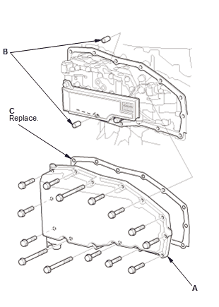
1. Remove the transmission fluid pan (A)
2. Remove the dowel pins (B)
3. Remove the gasket (C).
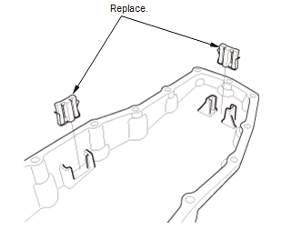
4. Clean the transmission magnet assembly. NOTE:
- Check the transmission magnet assembly for damage or dirt. If it is damaged or dirty, replace it.
- When you remove the transmission magnet assembly, replace it with new magnets.
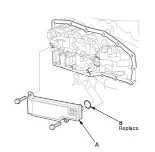
- 9. Transmission Fluid Strainer - Remove
1. Remove the transmission fluid strainer (A) with the O-ring (B).
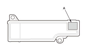
2. Clean the inlet opening (A) of the transmission fluid strainer thoroughly with compressed air 3. Check that it is in good condition and that the inlet opening is not clogged
4. Test the strainer by pouring clean transmission fluid through the inlet opening, and replace it if it is clogged or damaged.
- 10. Lower Valve Body Assembly - Remove
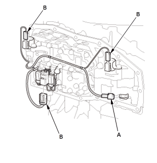
1. Remove the transmission fluid temperature sensor (A)
2. Disconnect the connectors (B).
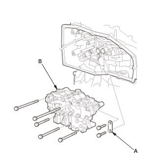
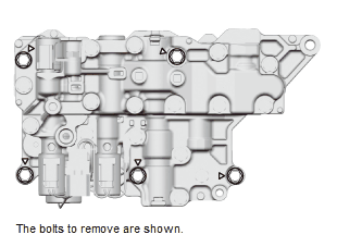
3. Remove the guide plate (A) 4. Remove the lower valve body assembly (B), and hold the lower valve body assembly.
NOTE:
- Check that the lower valve body assembly is free of solenoid wire harness A.
- Do not damage solenoid wire harnesses A and B while removing the lower valve body.
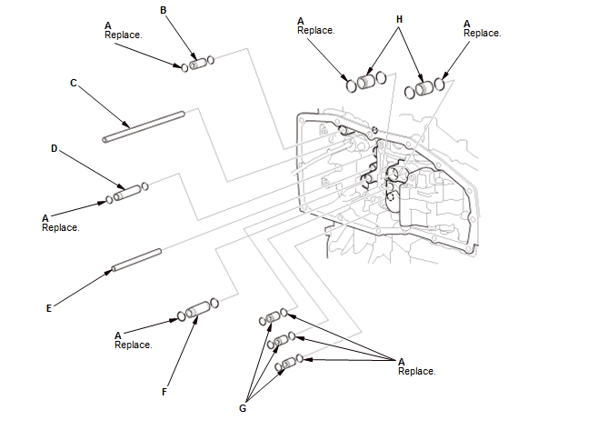
5. Remove these pipes with the O-rings (A):
- 10.9 x 26 mm pipe (B)
- 8 x 133.5 mm pipe (C)
- 12 x 56.7 mm pipe (D)
- 8 x 71.5 mm pipe (E)
- 14.3 x 36.2 mm pipe (F)
- 10.9 x 18.5 mm pipes (G)
- 18 x 18 mm pipes (H)
- 11. Solenoid Wire Harness A - Remove
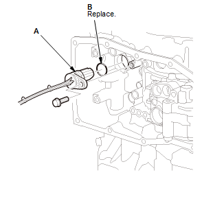
1. Remove solenoid wire harness A with the O-ring (B).
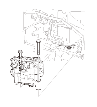
- 12. Transmission Fluid Pump - Remove
- 13. Transmission - Turn Transmission Upside Down
1. Turn the transmission upside down, and set it on the workbench to prevent damaging the end cover, always use wood blocks or equivalent materials between the transmission and the workbench.
- 14. Torque Converter Housing - Remove
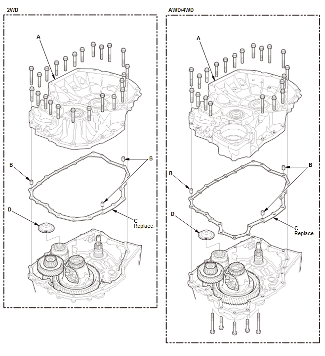
1. Remove the torque converter housing (A).
2. Remove the dowel pins (B)
3. Remove the gasket (C)
4. Remove the oil guide plate (D).
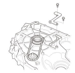
- 15. Lubrication Plate - Remove
- 16. Transmission Fluid Pump Drive Sprocket and Transmission Fluid Pump Drive Chain - Remove
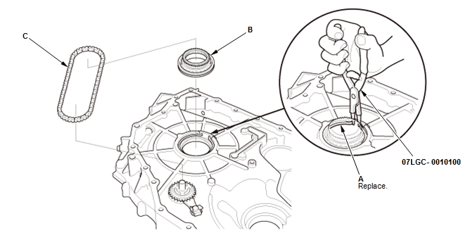
1. While expanding the snap ring (A) of the transmission fluid pump drive sprocket (B) using the snap ring pliers, remove the transmission fluid pump drive sprocket.
2. Remove the transmission fluid pump drive chain (C)
3. Remove the snap ring.
- 17. Transmission Fluid Pump Driven Sprocket - Remove
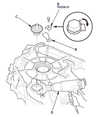
1. Pry down the lock tab of the lock washer (A)
2. Remove the lock washer and the bearing set plate (B)
3. Remove the transmission fluid pump driven sprocket (C) by heating the torque converter housing to about 212 °F (100 °C) using a heat gun (D).
NOTE: Do not heat the torque converter housing more than 212 °F (100 °C).
- 18. Final Drive Shaft Assembly and Differential Assembly - Remove
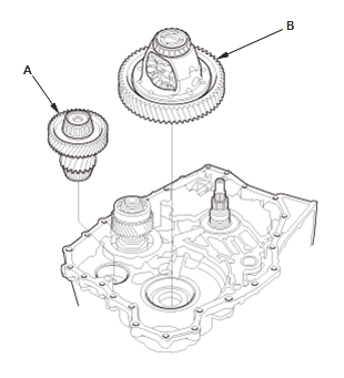
1. Remove the final drive shaft assembly (A) and the differential assembly (B).
- 19. Control Lever and Detent Lever - Remove
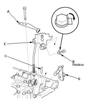
1. Remove the detent spring (A)
2. Pry down the lock tab of the lock washer (B), then remove the lock washer
3. Remove the 5 x 48 mm roller (C)
4. Remove the control lever (D) and the detent lever (E).
- 20. Manual Valve Body - Remove
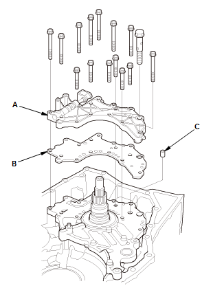
1. Remove the manual valve body (A) with the separator plate (B) and the dowel pin (C).
- 21. Stator Shaft - Remove
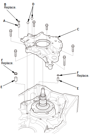
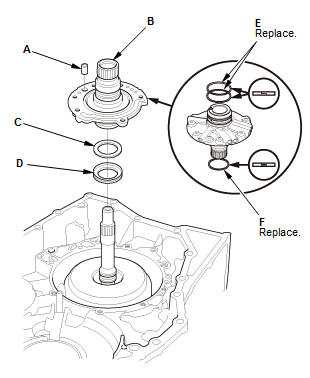
1. Remove the dowel pin (A) and the O-ring (B)
2. Remove the stator shaft flange (C)
3. Remove the check balls (D).
NOTE: Do not use a magnet to remove the check balls, it may magnetize the check balls
4. Remove the dowel pins (E) and the O-rings (F).
5. Remove the dowel pin (A) 6. Remove the stator shaft (B).
NOTE: Do not take out the needle bearing of the stator shaft
7. Remove the 32 x 42 mm thrust shim (C) and the 29.55 x 45 x 3.62 mm thrust needle bearing (D)
8. Remove the 47 mm sealing rings (E) and the 40 mm sealing ring (F).
- 22. Input Shaft Assembly and Planetary Carrier Assembly - Remove
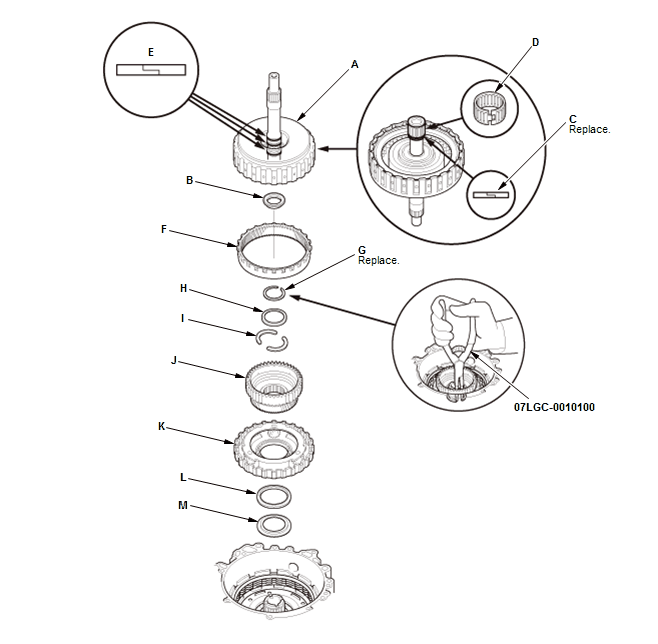
1. Remove the input shaft assembly (A) and the 24.5 x 39.1 x 3.2 mm thrust needle bearing (B).
2. Remove the 24 mm sealing ring (C)
3. Check the 20 x 24 x 17 mm needle bearing (D). If the 20 x 24 x 17 mm needle bearing is worn or damaged, replace it
4. Check the 27 mm sealing rings (E). If the 27 mm sealing rings are worn or damaged, replace the input shaft assembly.
NOTE: The 27 mm sealing rings and the input shaft assembly are not available separately. Replace them as a set
5. Remove the ring gear (F)
6. Remove the snap ring (G) using the snap ring pliers
7. Remove the cotter retainer (H), the 32.5 mm cotters (I), and the sun gear (J)
8. Remove the planetary carrier assembly (K), the 50 x 65 x 3 mm thrust washer (L), and the 40 x 63 x 5.5 mm washer (M).
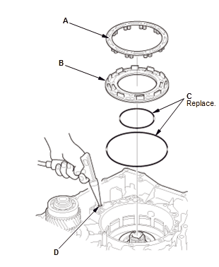
- 23. Reverse Brake - Remove
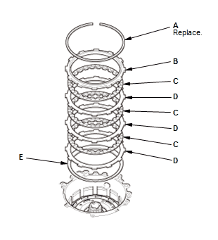
1. Remove the snap ring (A) using a flat-tip screwdriver
2. Remove the reverse brake end-plate (B)
3. Remove the reverse brake discs (C) and the reverse brake plates (D)
4. Remove the disc spring (E).
- 24. Reverse brake piston - Remove
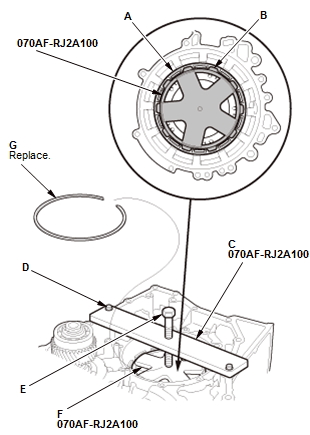
1. Put the reverse brake spring compressor on the spring retainer/return spring assembly (A).
NOTE: Be sure the attachment is set over the return springs, not on the reverse brake piston (B)
2. Install the plate (C) of the reverse brake spring compressor with facing the UP mark to the upside using 8 x 1.25 mm bolts (D)
3. Make sure that the reverse brake spring compressor pressure bolt (E) is properly installed on the dent in the surface of the reverse brake spring compressor (F)
4. Compress the return springs using the reverse brake spring compressor until the snap ring securing the spring retainer/return spring can be removed
5. Remove the snap ring (G) using a flat-tip screwdriver
6. Remove the reverse brake spring compressor.
7. Remove the spring retainer/return spring assembly (A) 8. Remove the reverse brake piston (B) with the O-rings (C), while applying air pressure to the reverse brake pressure circuit hole (D).
- 25. Transmission - Turn Transmission Upside Down.
1. Turn the transmission upside down, and set it on the workbench to prevent damaging the driven pulley shaft, always use wood blocks or equivalent materials between the transmission and the workbench
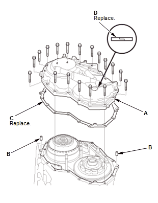
- 26. End Cover - Remove
1. Remove the end cover (A)
2. Remove the dowel pins (B) and the gasket (C)
3. Remove the sealing ring (D).
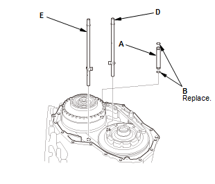
- 27. Pipe - Remove
1. Remove lubrication pipe D and lubrication pipe E
2. Remove the 12 x 89 mm pipe (A) with the O-rings (B).
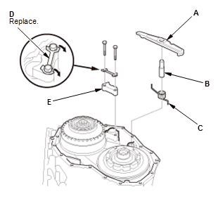
- 28. Parking Brake Pawl, Parking Shaft, and Parking Brake Rod Holder - Remove
1. Remove the parking brake pawl (A), the parking shaft (B), and the parking pawl spring (C)
2. Pry down the lock tabs of the lock washer (D)
3. Remove the lock washer and the parking brake rod holder (E).