CVT Transmission Disassembly and Reassembly: Reassembly
NOTE:
- Refer to the Exploded View as needed during this procedure.
- When you reassemble the transmission, apply a light coat of clean transmission fluid on oil seal, O-ring, and bearing. Also soak the forward clutch assembly and the reverse brake discs, in clean transmission fluid for at least 30 minutes prior to installation.
- Keep all foreign particles out of the transmission.
- Unless otherwise indicated, illustrations used in the procedure are for AWD/4WD.
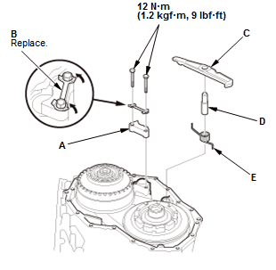
- 1. Parking Brake Pawl, Parking Shaft, and Parking Brake Rod Holder - Install
1. Install the parking brake rod holder (A) and a new lock washer (B)
2. Pry up the lock tab of the lock washer against the bolt head
3. Install the parking brake pawl (C) with the parking shaft (D) and the parking pawl spring (E).
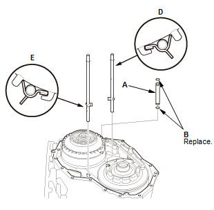
- 2. Pipe - Install
1. Install the 12 x 89 mm pipe (A) with new O-rings (B)
2. Install lubrication pipe D (8 x 234 mm) and lubrication pipe E (8 x 244 mm) in the direction shown.
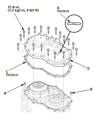
- 3. End Cover - Install
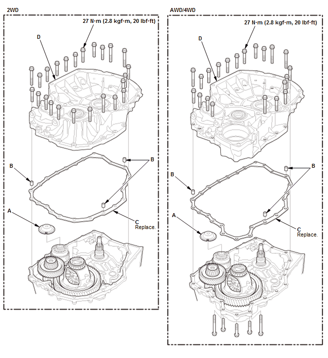
1. Install a new sealing ring (A)
2. Install the dowel pins (B) and a new gasket (C)
3. Install the end cover (D), and tighten them in a crisscross pattern in at least two steps.
- 4. Transmission - Turn Transmission Upside Down
1. Turn the transmission upside down, and set it on the workbench to prevent damaging the end cover, always use wood blocks or equivalent materials between the transmission and the workbench.
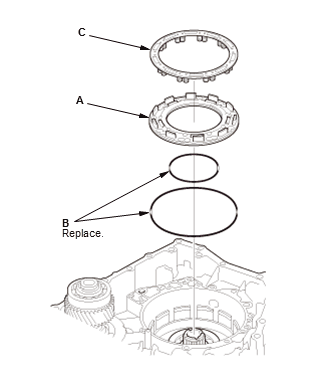
- 5. Reverse brake piston - Install
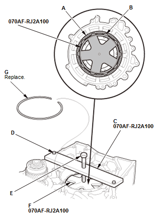
1. Install the reverse brake piston (A) using new O-rings (B)
2. Install the spring retainer/return spring assembly (C).
3. Put the reverse brake spring compressor on the spring retainer/return spring assembly (A). NOTE: Be sure the attachment is set over the return springs, not on the reverse brake piston (B)
4. Install the plate (C) of the reverse brake spring compressor with facing the UP mark to the upside using 8 x 1.25 mm bolts (D)
5. Make sure that the reverse brake spring compressor pressure bolt (E) is properly installed on the dent in the surface of the reverse brake spring compressor (F)
6. Compress the return springs using the reverse brake spring compressor until the snap ring securing the spring retainer/return spring can be installed
7. Install a new snap ring (G) using a flat-tip screwdriver.
NOTE:
- Be careful not to deform the snap ring by opening/closing it excessively.
- Make sure the snap ring is firmly installed in the groove.
8. Remove the reverse brake spring compressor.
- 6. Reverse Brake - Install
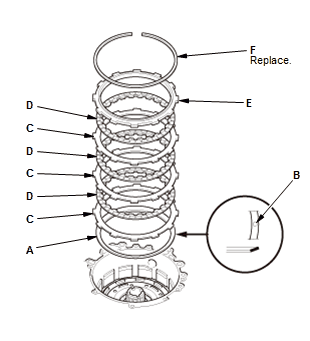
1. Install the disc spring (A).
NOTE: Be sure to install the disc spring with the indented mark (B) facing upward
2. Starting with the reverse brake discs (C), alternately install reverse brake plates (D)
3. Install the reverse brake end-plate (E) with the flat side toward the top disc
4. Install a new snap ring (F) using a flat-tip screwdriver.
NOTE:
- Be careful not to deform the snap ring by opening/closing it excessively.
- Make sure the snap ring is firmly installed in the groove.
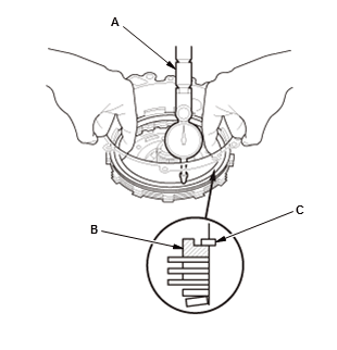
5. Set a dial indicator (A) on the reverse brake end-plate (B) 6. Zero the dial indicator with the reverse brake end-plate is lifted up to the snap ring (C)
7. Release the reverse brake end-plate to lower the reverse brake end-plate.
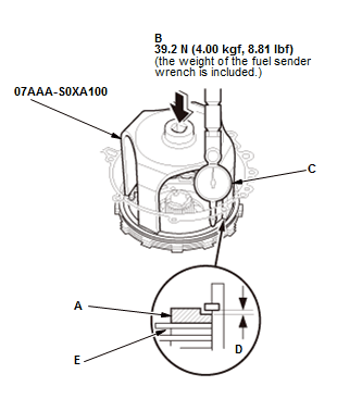
8. Put the fuel sender wrench on the reverse brake end-plate (A) 9. Press the fuel sender wrench down with 39.2 N (4.00 kgf, 8.81 Ibf) (the weight of the fuel sender wrench is included) (B) using a force gauge, and read the dial indicator (C).
- 10. The dial indicator reads the clearance (D) between the reverse brake end-plate and the top disc (E). Take measurements in at least three places, and use the average as the actual clearance.
Clearance Between Reverse Brake End-Plate and Top Disc Standard: 0.9-1.1 mm (0.035-0.043 in)
- 11. If the clearance is out of the standard, remove the reverse brake end-plate, and measure its thickness.
- 12. Select a new reverse brake end-plate.
- 13. Install a new reverse brake end-plate, then recheck the clearance.
No. Thickness 2 4.6 mm (0.181 in) 3 4.7 mm (0.185 in) 4 4.8 mm (0.189 in) 5 4.9 mm (0.193 in) 6 5.0 mm (0.197 in) 7 5.1 mm (0.201 in) 8 5.2 mm (0.205 in) 9 5.3 mm (0.209 in) 10 5.4 mm (0.213 in) 11 5.5 mm (0.217 in) 12 5.6 mm (0.220 in) 13 5.7 mm (0.224 in) 14 5.8 mm (0.228 in) 15 5.9 mm (0.232 in) 16 6.0 mm (0.236 in) 17 6.1 mm (0.240 in) 18 6.2 mm (0.244 in) - 7. Planetary Carrier Assembly and Input Shaft Assembly - Install
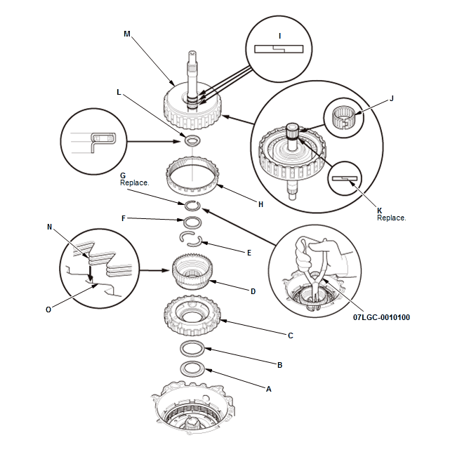
1. Install the 40 x 63 x 5.5 mm washer (A), the 50 x 65 x 3 mm thrust washer (B), and the planetary carrier assembly (C).
2. Install the sun gear (D), the 32.5 mm cotters (E), and the cotter retainer (F)
3. Install a new snap ring (G) using the snap ring pliers.
NOTE:
- Be careful not to deform the snap ring by opening/closing it excessively.
- Make sure the snap ring is firmly installed in the groove.
4. Install the ring gear (H)
5. Check the 27 mm sealing rings (I). If the 27 mm sealing rings are worn or damaged, replace the input shaft assembly.
NOTE: The 27 mm sealing rings and the input shaft assembly are not available separately. Replace them as a set
6. Check the 20 x 24 x 17 mm needle bearing (J). If the 20 x 24 x 17 mm needle bearing is worn or damaged, replace it
7. Install a new 24 mm sealing ring (K)
8. Install the 24.5 x 39.1 x 3.2 mm thrust needle bearing (L) in the direction shown
9. Install the input shaft assembly (M) by aligning the clutch discs (N) with the splines (O), and push in the Input shaft assembly until the top disc.
- 8. Stator Shaft - Install
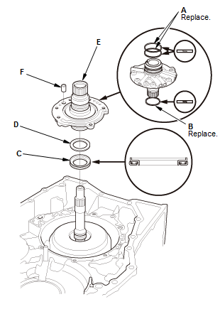
1. Install new 47 mm sealing rings (A) and a new 40 mm sealing ring (B)
2. Install the 29.55 x 45 x 3.62 mm thrust needle bearing (C) in the direction shown
3. Install the 32 x 42 mm thrust shim (D)
4. Install the stator shaft (E)
5. Install the dowel pin (F).
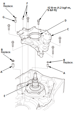
6. Install the dowel pins (A) and new O-rings (B) 7. Install the stator shaft flange (C) by aligning the hole (D) of the stator shaft flange with the dowel pin (E) of the stator shaft
8. Install the check balls (F).
NOTE: Do not use a magnet to install the check balls, it may magnetize the check balls
9. Install the dowel pin (G) and a new O-ring (H).
- 9. Manual Valve Body - Install
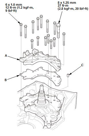
1. Install the manual valve body (A) with the separator plate (B) and the dowel pin (C).
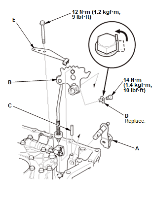
- 10. Control Lever and Detent Lever - Install
1. Install the control lever (A) and the detent lever (B)
2. Install the 5 x 48 mm roller (C)
3. Secure the control shaft with a new lock washer (D), then pry up the lock tab of the lock washer against the bolt head
4. Install the detent spring (E).
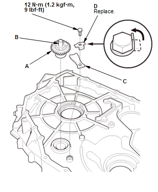
- 11. Transmission Fluid Pump Driven Sprocket - Install
1. Install the transmission fluid pump driven sprocket (A) until it bottoms.
NOTE: Do not tap on transmission fluid pump driven sprocket shaft (B) when installing the transmission fluid pump driven sprocket
2. Check that the bearing groove aligns with the torque converter housing surface, then install the bearing set plate (C) with aligning the bearing groove
3. Install the bearing set plate with a new lock washer (D)
4. Pry up the lock tab of the lock washer against the bolt head.
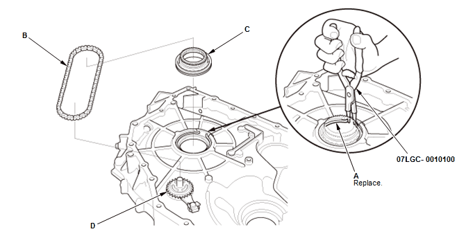
- 12. Transmission Fluid Pump Drive Sprocket and Transmission Fluid Pump Drive Chain - Install a new snap ring (A).
NOTE:
- Be careful not to deform the snap ring by opening/closing it excessively.
- Make sure the snap ring is firmly installed in the groove.
2. Install the transmission fluid pump drive chain (B) by aligning sprocket tooth on the transmission fluid pump drive sprocket (C) and the transmission fluid pump driven sprocket (D)
3. Install the transmission fluid pump drive sprocket and the transmission fluid pump drive chain together
4. While expanding the snap ring using the snap ring pliers, install the transmission fluid pump drive sprocket.
NOTE: Be careful not to deform the snap ring by opening/closing it excessively
5. Release the snap ring pliers, then push the transmission fluid pump drive sprocket down until the snap ring snaps in place around it.
NOTE: Make sure the snap ring is firmly installed in the groove.
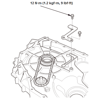
- 13. Lubrication Plate - Install
- 14. Final Drive Shaft Assembly and Differential Assembly - Install
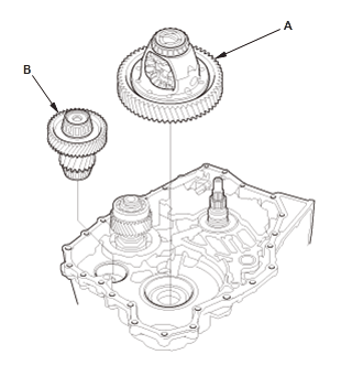
1. Install the differential assembly (A) and the final drive shaft assembly (B).
- 15. Torque Converter Housing - Install the oil guide plate (A).
2. Install the dowel pins (B) and a new gasket (C)
3. Install the torque converter housing (D), and tighten them in a crisscross pattern in at least two steps.
- 16. Transmission - Turn Transmission Upside Down
1. Turn the transmission upside down, and set it on the workbench to prevent damaging the input shaft, always use wood blocks or equivalent materials between the transmission and the workbench.
- 17. Transmission Fluid Pump - Install
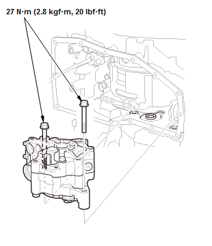
1. Apply transmission fluid to the transmission fluid pump shaft splines
2. Install the transmission fluid pump.
- 18. Solenoid Wire Harness A - Install
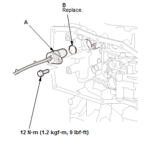
1. Install solenoid wire harness A with a new O-ring (B).
NOTE: Install solenoid wire harness A horizontally to prevent damaging the O-ring.
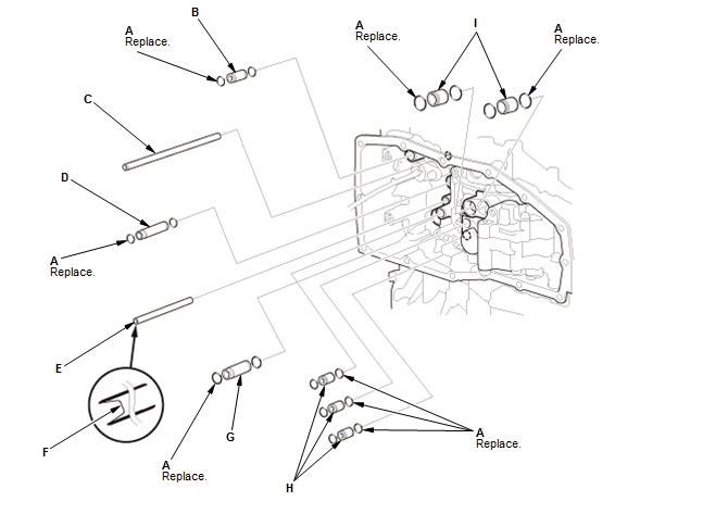
- 19. Lower Valve Body Assembly - Install these pipes with new O-rings (A):
- 10.9 x 26 mm pipe (B)
- 8 x 133.5 mm pipe (C)
- 12 x 56.7 mm pipe (D)
- 8 x 71.5 mm pipe (E)
NOTE: Be sure to install the 8 x 71.5 mm pipe with the filter end (F) toward the lower valve body assembly.
- 14.3 x 36.2 mm pipe (G)
- 10.9 x 18.5 mm pipes (H)
- 18 x 18 mm pipes (I)
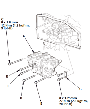
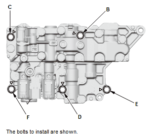
2. Install the lower valve body assembly (A), and tighten them in a crisscross pattern in at least two steps. NOTE:
- Do not pinch the solenoid wire harnesses.
- Do not damage the solenoid wire harnesses while installing the lower valve body assembly.
B 90 mm (3.54 in) C 80 mm (3.15 in) D 65 mm (2.56 in) E 55 mm (2.17 in) F 40 mm (1.57 in) 3. Install the guide plate (G).
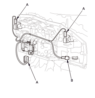
4. Connect the connectors (A) 5. Install the transmission fluid temperature sensor (B).
- 20. Transmission Fluid Strainer - Install
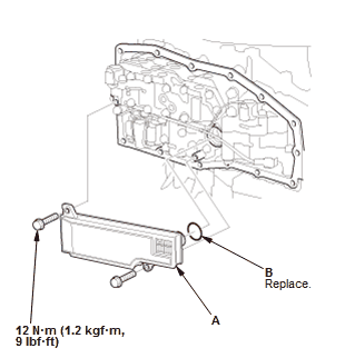
1. Install the transmission fluid strainer (A) with a new O-ring (B).
NOTE:
- Install the transmission fluid strainer carefully to prevent damaging the O-ring.
- Do not pinch the solenoid wire harnesses.
- 21. Transmission Fluid Pan - Install
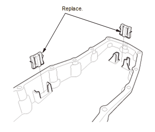
1. Install new transmission magnets.
NOTE: When you remove the transmission magnet assembly, replace it with new magnets.
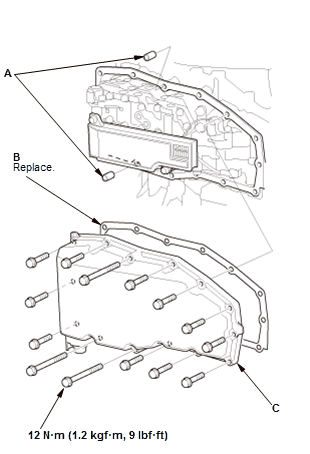
2. Install the dowel pins (A) and a new gasket (B) 3. Install the transmission fluid pan (C), and tighten them in a crisscross pattern in at least two steps.
NOTE: Do not pinch the solenoid wire harnesses.
- 22. Transmission - Turn Transmission Upside Down
1. Turn the transmission upside down, and set it on the workbench to prevent damaging the input shaft, always use wood blocks or equivalent materials between the transmission and the workbench.
- 23. CVT Speed Sensor - Install
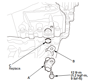
1. Install the CVT speed sensor (A) and the sensor washer (B) with a new O-ring (C).
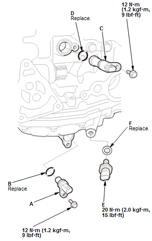
- 24. CVT Drive Pulley Speed Sensor, Torque Converter Turbine Speed Sensor, and CVT Driven Pulley Pressure Sensor - InstallFig 5: CVT Drive Pulley Speed Sensor, Torque Converter Turbine Speed Sensor, & CVT Driven Pulley Pressure Sensor With Torque Specifications
 Courtesy of HONDA, U.S.A., INC.
1. Install the CVT drive pulley speed sensor (A) with a new O-ring (B)
2. Install the torque converter turbine speed sensor (C) with a new O-ring (D)
3. Install the CVT driven pulley pressure sensor (E) with a new sealing washer (F).
NOTE: Be careful not to damage the plastic part.
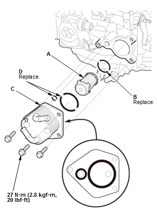
- 25. Transmission Fluid Warmer and Transmission Fluid Warmer Strainer - Install
 Courtesy of HONDA, U.S.A., INC.
1. Clean the mounting surfaces of the transmission housing
2. Install the transmission fluid warmer strainer (A) with a new O-ring (B)
3. Install the transmission fluid warmer (C) with new O-rings (D).
NOTE: The transmission fluid warmer is aluminum part. Be careful not to damage the transmission fluid warmer.
- 26. Transmission Range Switch/Control Shaft Cover - Install
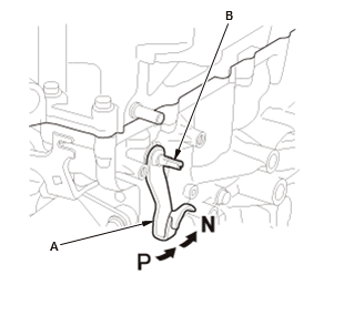
1. Turn the control lever (A) to the P position.
NOTE: Do not use the control shaft (B) to adjust the shift position. If the control shaft tips are squeezed together it will cause a faulty signal or position due to play between the control shaft and the transmission range switch
2. Turn the control lever back two clicks to the N position.
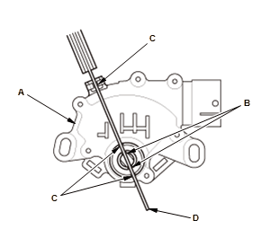
3. Set the transmission range switch (A) to the N position. Align the cutouts (B) on the rotary-frame with the N positioning cutouts (C) on the transmission range switch, then put a 2.0 mm (0.079 in) feeler gauge (D) in the cutouts to hold the transmission range switch in the N position. NOTE: Be sure to use a 2.0 mm (0.079 in) feeler gauge or equivalent to hold the transmission range switch in the N position.
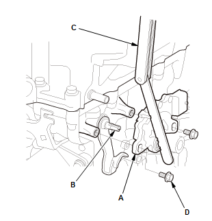
4. Install the transmission range switch (A) gently on the control shaft (B) while holding it in the N position with the 2.0 mm (0.079 in) feeler gauge (C) 5. Loosely install the bolts (D).
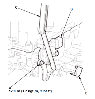
6. Tighten the bolts (A) on the transmission range switch (B) while you continue to hold the N position. NOTE: Do not move the transmission range switch when tightening the bolts
7. Remove the feeler gauge (C)
8. Install the control shaft cover (D).
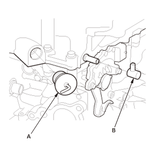
- 27. Transmission Fluid Filler Cap and Breather Cap - Install
1. Install the transmission fluid filler cap (A) and the breather cap (B).
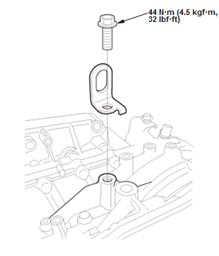
- 28. Transmission Hanger - Install