Forward Clutch Clearance Inspection: Inspection
- 1. Input Shaft Assembly - Remove
- 2. Forward Clutch Clearance - Inspect
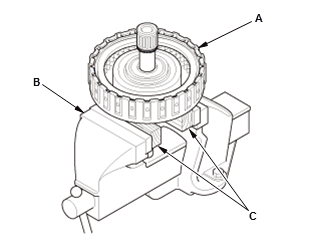
1. Secure the input shaft assembly (A) in a bench vise (B) with wood blocks (C).
NOTE: After this procedure, remove any wood chips that may be stuck to the spline.
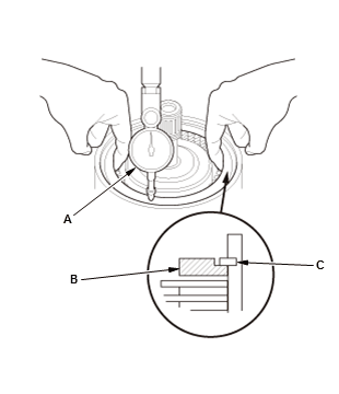
2. Set a dial indicator (A) on the clutch end-plate (B) 3. Zero the dial indicator with the clutch end-plate is lifted up to the snap ring (C)
4. Release the clutch end-plate to lower the clutch end-plate.
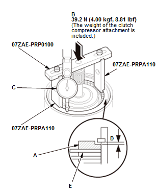
5. Put the clutch compressor attachment with the clutch compressor attachment 64 mm on the clutch end-plate (A). NOTE: Be sure to set the clutch compressor attachment with the indented mark facing upward
6. Press the clutch compressor attachment down with 39.2 N (4.00 kgf, 8.81 Ibf) (the weight of the clutch compressor attachment is included) (B) using a force gauge, and read the dial indicator (C)
7. The dial indicator reads the clearance (D) between the clutch end-plate and the top disc (E). Take measurements in at least three places, and use the average as the actual clearance.
Clearance Between Clutch End-Plate and Top Disc Standard: 0.8-1.0 mm (0.031-0.039 in)
8. If the clearance is out of the standard, replace the input shaft assembly.
- 3. Input Shaft Assembly - Install