Input Shaft Thrust Clearance Adjustment: Adjustment
NOTE: If the transmission housing, the torque converter housing, the input shaft assembly, the stator shaft, the 29.55 x 45 x 3.62 mm thrust needle bearing, or the torque converter housing gasket were replaced, the input shaft thrust clearance must be adjusted.
- 1. Input Shaft Thrust Clearance - Adjust
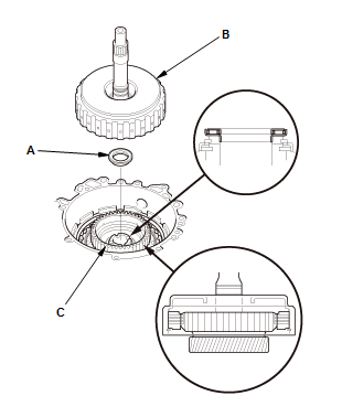
1. Install the 24.5 x 39.1 x 3.2 mm thrust needle bearing (A) in the direction shown
2. Wiggle the forward clutch discs of the input shaft assembly (B) back and forth as it goes into the sun gear (C), and push in the Input shaft assembly until the top disc.
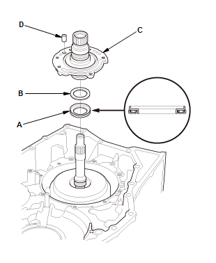
3. Install the 29.55 x 45 x 3.62 mm thrust needle bearing (A) in the direction shown 4. Install the 32 x 42 mm thrust shim (B).
NOTE: If you install a new 32 x 42 mm thrust shim, use the same thickness shim as the old one, or use the 2.10 mm (0.0827 in) thickness of the 32 x 42 mm thrust shim
5. Install the stator shaft (C)
6. Install the dowel pin (D).
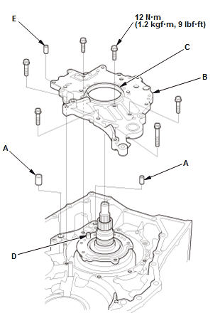
7. Install the dowel pins (A) 8. Install the stator shaft flange (B) by aligning the hole (C) of the stator shaft flange with the dowel pin (D) of the stator shaft
9. Install the dowel pin (E).
 Courtesy of HONDA, U.S.A., INC.
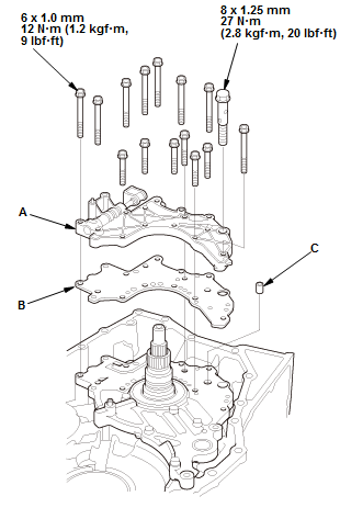
10. Install the manual valve body (A) with the separator plate (B) and the dowel pin (C).
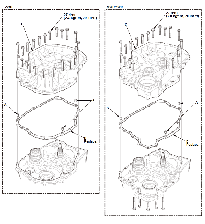
11. Install the dowel pins (A).
12. Install a new gasket (B)
13. Install the torque converter housing (C), and tighten them in a crisscross pattern in at least two steps.
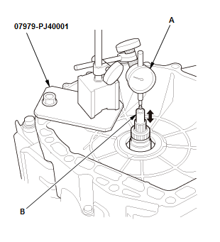
14. Install the magnet stand base 15. Set a dial indicator (A) on the tip of the input shaft (B)
16. Zero the dial indicator, then lift the input shaft up.
- 17. The dial indicator reads the input shaft thrust clearance. Take measurements in at least three places, and use the average as the actual clearance.
Standard: 0.15-0.25 mm (0.0059-0.0098 in)
- 18. If the clearance is out of the standard, remove the 32 x 42 mm thrust shim, and measure its thickness.
- 19. Select a 32 x 42 mm thrust shim.
- 20. Install a new 32 x 42 mm thrust shim, then recheck the thrust clearance.
No. Thickness A 1.65 mm (0.0650 in) B 1.70 mm (0.0669 in) C 1.75 mm (0.0689 in) D 1.80 mm (0.0709 in) E 1.85 mm (0.0728 in) F 1.90 mm (0.0748 in) G 1.95 mm (0.0768 in) H 2.00 mm (0.0787 in) I 2.05 mm (0.0807 in) J 2.10 mm (0.0827 in) K 2.15 mm (0.0846 in) L 2.20 mm (0.0866 in) M 2.25 mm (0.0886 in) N 2.30 mm (0.0906 in) O 2.35 mm (0.0925 in) P 2.40 mm (0.0945 in) Q 2.45 mm (0.0965 in) R 2.50 mm (0.0984 in) S 2.55 mm (0.1004 in) T 2.60 mm (0.1024 in) - 17. The dial indicator reads the input shaft thrust clearance. Take measurements in at least three places, and use the average as the actual clearance.