Shift Position Indicator Circuit Troubleshooting
A/T Gear Position Indicator Circuit Troubleshooting
NOTE: Check for CVT system DTCs. If any DTCs are present, troubleshoot those first.
CVT System
| DTC Description | Confirmed DTC | Pending DTC | Freeze Frame |
|---|---|---|---|
DTC (CVT)
- 1. Shift cable adjustment check:
- 1. Make sure the shift cable is properly adjusted .
Is the shift cable adjusted properly?
YES
The shift cable adjustment is OK. Go to step 2.
NO
Adjust the shift cable , then recheck.
- 2. Gauge control module lost of communication DTC check:
- 1. Check for DTCs in BODY ELECTRICAL with the HDS.
DTC Description DTC U0100 Gauge control module lost communication with PCM Is DTC U0100 indicated?
YES
Go to DTC U0100 troubleshooting in the gauge control module .
NO
Go to step 3.
- 3. Shift position indicator drive circuit check:
Does the shift position indicator blink while checking?
YES
Go to step 4.
NO
Failure of shift position indicator drive circuit in the gauge control module, replace the gauge control module .
- 4. Transmission range switch signal check 1:
- 1. Turn the vehicle to the ON mode.
- 2. Compare the transmission range switch signal inputs with the HDS to the following table, in each shift lever position/mode.
Signal
Threshold
Current conditions
P
R
N
D
S
L
ValuesUnit A/T P Switch ON OFF OFF OFF OFF OFF A/T R Switch OFF ON OFF OFF OFF OFF A/T N Switch OFF OFF ON OFF OFF OFF A/T D Switch OFF OFF OFF ON OFF OFF A/T S Switch OFF OFF OFF OFF ON OFF A/T L Switch OFF OFF OFF OFF OFF ON Do the transmission range switch signals match?
YES
The transmission range switch signal is OK. Update the PCM if it does not have the latest software , or substitute a known-good PCM , then recheck. If the symptom goes away, replace the original PCM .
NO
Go to step 5.
- 5. Transmission range switch signal check 2:
- 1. Compare the transmission range switch signal inputs with the HDS to the following table, in each shift lever position/mode.
Signal
Threshold
Current conditions
P
R
N
D
S
L
ValuesUnit A/T P Switch ON OFF OFF OFF OFF OFF A/T R Switch OFF ON OFF OFF OFF OFF A/T N Switch OFF OFF ON OFF OFF OFF A/T D Switch OFF OFF OFF ON OFF OFF A/T S Switch OFF OFF OFF OFF ON OFF A/T L Switch OFF OFF OFF OFF OFF ON Do all signals remain OFF?
YES
Go to step 8.
NO
Record the abnormal circuit, then go to step 6.
- 6. Transmission range switch check:
- 1. Turn the vehicle to the OFF (LOCK) mode.
- 2. Disconnect the following connector.
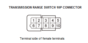
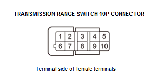
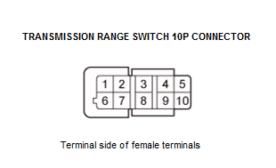
Transmission range switch 10P connector - 3. Connect the transmission range switch 10P connector terminal that incorrectly indicates ON in step 5 to body ground with a jumper wire; refer to the following table.
Signal
Transmission range switch 10P connector
Terminal numberTerminal name A/T P Switch 5 ATP-P A/T R Switch 4 ATP-R A/T N Switch 9 ATP-N A/T D Switch 3 ATP-D A/T S Switch 8 ATP-S A/T L Switch 2 ATP-L - 4. Turn the vehicle to the ON mode.
- 5. Check the parameter(s) below that did not indicate ON with the HDS.
Signal
Threshold
Current conditions
P
R
N
D
S
L
ValuesUnit A/T P Switch ON OFF OFF OFF OFF OFF A/T R Switch OFF ON OFF OFF OFF OFF A/T N Switch OFF OFF ON OFF OFF OFF Signal
Threshold
Current conditions
P
R
N
D
S
L
ValuesUnit A/T D Switch OFF OFF OFF ON OFF OFF A/T S Switch OFF OFF OFF OFF ON OFF A/T L Switch OFF OFF OFF OFF OFF ON Does the transmission range switch indicate ON?
YES
Replace the transmission range switch .
NO
The transmission range switch is OK. Go to step 7.
- 7. Open wire check (corresponding line):
- 1. Turn the vehicle to the OFF (LOCK) mode.
- 2. Jump the SCS line with the HDS, and wait more than 1 minute.
SCS Short
- 3. Disconnect the following connector.
PCM connector C (51P) - 4. Check for continuity between the transmission range switch connector terminal and the PCM terminal of the input which indicated OFF. Refer to the following table.
ATP-P ATP-R ATP-N ATP-D ATP-S ATP-L PCM C34 C27 C24 C25 C43 C44 Transmission range switch 5 4 9 3 8 2 Is there continuity?
YES
The transmission range switch signal is OK. Update the PCM if it does not have the latest software , or substitute a known-good PCM , then recheck. If the symptom goes away, replace the original PCM .
NO
Repair an open in the wire between the corresponding transmission range switch connector terminal and the PCM.
- 8. Open wire check (PG line):
- 1. Turn the vehicle to the OFF (LOCK) mode.
- 2. Disconnect the following connector.
Transmission range switch 10P connector - 3. Check for continuity between test points 1 and 2.
Test condition Vehicle OFF (LOCK) mode Transmission range switch 10P connector: disconnected Test point 1 Transmission range switch 10P connector No. 1 Test point 2 Body ground Is there continuity?
YES
The PG wire is OK, replace the transmission range switch .
NO
Repair an open in the PG wire between the transmission range switch and body ground (G101), or repair poor body ground (G101).