DTC B0096-87: No Signal From the Right Side Impact Sensor (first)
Special Tools Required
SRS Inflator Simulator 07SAZ-TB4011A
SRS Simulator Lead L 070AZ-SNAA300
NOTE:
- Before doing this troubleshooting procedure, find out if the vehicle was in a collision. If so, verify that all the required components were replaced with new components of the correct part number, and that they were properly installed .
- Before doing this troubleshooting procedure, review SRS Precautions and Procedures , General Troubleshooting Information , and 12 Volt Battery Terminal Disconnection and Reconnection .
- Before replacing the SRS unit, check the SRS unit software version with the HDS. If the software version is not the latest, update the SRS unit software , and retest.
| DTC Description | DTC |
|---|---|
| B0096-87 No signal from the right side impact sensor (first) |
DTC (SRS)
- 1. DTC check:
- 1. Clear the DTCs with the HDS .
- 2. Turn the vehicle to the ON mode, then wait for 10 seconds.
- 3. Check for DTCs with the HDS .
DTC Description DTC B0096-87 No signal from the right side impact sensor (first) B0097-87 No signal from the right side impact sensor (second) Are DTCs indicated?
Only DTC B0096-87
Go to step 2.
DTC B0096-87 and DTC B0097-87
Replace the right side impact sensor (first) - Refer to: Side Impact Sensor (First) Removal and InstallationSide Impact Sensor (Second) Removal and Installation , then clear the DTC.
NO DTC
Intermittent failure, the system is OK at this time. Go to Troubleshooting Intermittent Failures . If another DTC is indicated, troubleshoot the DTC.
- 2. Shorted wire check (RS1+ line to RS1- line):
- 1. Turn the vehicle to the OFF (LOCK) mode.
- 2. Disconnect the negative cable from the 12 volt battery, then wait at least 3 minutes.
- 3. Disconnect the following connectors.
SRS unit connector B (39P) Right side impact sensor (first) 4P connector (on the floor wire harness) - 4. Measure the resistance between test points 1 and 2.
Test condition Vehicle OFF (LOCK) mode SRS unit connector B (39P): disconnected Right side impact sensor (first) 4P connector (on the floor wire harness): disconnected Test point 1 SRS unit connector B (39P) No. 26 Test point 2 SRS unit connector B (39P) No. 27 Is there an open circuit, or at least 1 MΩ?
YES
The RS1+ and RS1- wires are not shorted. Go to step 3.
NO
Short to another wire in the floor wire harness between the SRS unit and the right side impact sensor (first); replace the floor wire harness, then clear the DTC.
- 3. Shorted wire check (RS1+, RS1- lines):
- 1. Measure the resistance between test points 1 and 2.
Test condition Vehicle OFF (LOCK) mode SRS unit connector B (39P): disconnected Right side impact sensor (first) 4P connector (on the floor wire harness): disconnected Test point 1 SRS unit connector B (39P) No. 26 Test point 2 Body ground Test point 1 SRS unit connector B (39P) No. 27 Test point 2 Body ground Is there an open circuit, or at least 1 MΩ?
YES
The RS1+ and RS1- wires are not shorted. Go to step 4.
NO
Short to ground in the floor wire harness between the SRS unit and the right side impact sensor (first); replace the floor wire harness, then clear the DTC.
- 4. Shorted wire check (RS1+, RS1- lines to power):
- 1. Reconnect the negative cable to the 12 volt battery.
- 2. Turn the vehicle to the ON mode.
- 3. Measure the voltage between test points 1 and 2.
Test condition Vehicle ON mode SRS unit connector B (39P): disconnected Right side impact sensor (first) 4P connector (on the floor wire harness): disconnected Test point 1 SRS unit connector B (39P) No. 26 Test point 2 Body ground Test point 1 SRS unit connector B (39P) No. 27 Test point 2 Body ground Is there 0.2 V or less?
YES
The RS1+ and RS1- wires are not shorted to power. Go to step 5.
NO
Short to power in the floor wire harness between the SRS unit and the right side impact sensor (first); replace the floor wire harness, then clear the DTC.
- 5. Open wire check (RS1+, RS1- lines):
- 1. Turn the vehicle to the OFF (LOCK) mode.
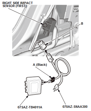
- 2. Connect the black terminal (A) of SRS simulator lead L to the SRS inflator simulator (jumper connector), then connect SRS simulator lead L to the right side impact sensor (first) 4P connector (B) on the floor wire harness.
- 3. Measure the resistance between test points 1 and 2.
Test condition Vehicle OFF (LOCK) mode SRS unit connector B (39P): disconnected Right side impact sensor (first) 4P connector (on the floor wire harness): disconnected Right side impact sensor (first) 4P connector (on the floor wire harness): connected to SRS simulator lead L Test point 1 SRS unit connector B (39P) No. 26 Test point 2 SRS unit connector B (39P) No. 27 Is there 1.0 Ω or less?
YES
The RS1+ and RS1- wires are OK. Replace the right side impact sensor (first) - Refer to: Side Impact Sensor (First) Removal and InstallationSide Impact Sensor (Second) Removal and Installation , then clear the DTC, and retest. If the DTC is still present, replace the SRS unit .
NO
Open in the floor wire harness between the SRS unit and the right side impact sensor (first); replace the floor wire harness, then clear the DTC.