DTC 46-1x: No Signal From the Right Side Impact Sensor (second)
NOTE:
- Before doing this troubleshooting procedure, find out if the vehicle was in a collision. If so, verify that all the required components were replaced with new components, of the correct part number, and that they were properly installed .
- Before doing this troubleshooting procedure, review SRS Precautions and Procedures , General Troubleshooting Information , and 12 Volt Battery Terminal Disconnection and Reconnection .
- Before replacing the SRS unit, check the SRS unit software version with the HDS. If the software version is not the latest, update the SRS unit software , and retest.
- 1. DTC check:
1. Clear the DTCs with the HDS .
2. Turn the vehicle to the ON mode, then wait for 10 seconds.
3. Check for DTCs with the HDS .
Are DTCs indicated?
Only DTC 46-11
Go to step 2.
DTC 46-1x (except 46-11)
Replace the right side impact sensor (second) - Refer to: Side Impact Sensor (First) Removal and InstallationSide Impact Sensor (Second) Removal and Installation , then clear the DTC.
NO DTC
Intermittent failure, the system is OK at this time. Go to Troubleshooting Intermittent Failures . If another DTC is indicated, troubleshoot the DTC.
- 2. Shorted wire check (RS2+ line to RS2- line):
1. Turn the vehicle to the OFF (LOCK) mode.
2. Disconnect the negative cable from the 12 volt battery, then wait at least 3 minutes.
3. Disconnect the following connectors.
Right side impact sensor (first) 4P connector (on the floor wire harness) Right side impact sensor (second) 2P connector (on the floor wire harness) 4. Measure the resistance between test points 1 and 2.
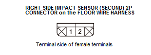
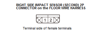
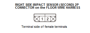
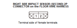
Test condition Vehicle OFF (LOCK) mode Right side impact sensor (first) 4P connector (on the floor wire harness): disconnected Right side impact sensor (second) 2P connector (on the floor wire harness): disconnected Test point 1 Right side impact sensor (second) 2P connector No. 1 (on the floor wire harness) Test point 2 Right side impact sensor (second) 2P connector No. 2 (on the floor wire harness) Is there an open circuit, or at least 1 MΩ?
YES
The RS2+ and RS2- wires are not shorted. Go to step 3.
NO
Short to another wire in the floor wire harness between the right side impact sensor (first) and the right side impact sensor (second); replace the floor wire harness, then clear the DTC.
- 3. Shorted wire check (RS2+, RS2- lines):
1. Measure the resistance between test points 1 and 2.
Test condition Vehicle OFF (LOCK) mode Right side impact sensor (first) 4P connector (on the floor wire harness): disconnected Right side impact sensor (second) 2P connector (on the floor wire harness): disconnected Test point 1 Right side impact sensor (second) 2P connector No. 2 (on the floor wire harness) Test point 2 Body ground Test point 1 Right side impact sensor (second) 2P connector No. 1 (on the floor wire harness) Test point 2 Body ground Is there an open circuit, or at least 1 MΩ?
YES
The RS2+ and RS2- wires are not shorted. Go to step 4.
NO
Short to ground in the floor wire harness between the right side impact sensor (first) and the right side impact sensor (second); replace the floor wire harness, then clear the DTC.
- 4. Shorted wire check (RS2+, RS2- lines to power):
1. Reconnect the negative cable to the 12 volt battery.
2. Turn the vehicle to the ON mode.
3. Measure the voltage between test points 1 and 2.
Test condition Vehicle ON mode Right side impact sensor (first) 4P connector (on the floor wire harness): disconnected Right side impact sensor (second) 2P connector (on the floor wire harness): disconnected Test point 1 Right side impact sensor (second) 2P connector No. 2 (on the floor wire harness) Test point 2 Body ground Test point 1 Right side impact sensor (second) 2P connector No. 1 (on the floor wire harness) Test point 2 Body ground Is there 0.2 V or less?
YES
The RS2+ and RS2- wires are not shorted to power. Go to step 5.
NO
Short to power in the floor wire harness between the right side impact sensor (first) and the right side impact sensor (second); replace the floor wire harness, then clear the DTC.
- 5. Open wire check (RS2+, RS2- lines):
1. Turn the vehicle to the OFF (LOCK) mode.
2. Connect terminals A and B with a jumper wire.
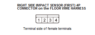
Terminal A Right side impact sensor (first) 4P connector No. 1 (on the floor wire harness) Terminal B Right side impact sensor (first) 4P connector No. 4 (on the floor wire harness) 3. Measure the resistance between test points 1 and 2.
Test condition Vehicle OFF (LOCK) mode Right side impact sensor (first) 4P connector (on the floor wire harness): disconnected Right side impact sensor (second) 2P connector (on the floor wire harness): disconnected Right side impact sensor (first) 4P connector terminals No. 1 and No. 4 (on the floor wire harness): jumped Test point 1 Right side impact sensor (second) 2P connector No. 1 (on the floor wire harness) Test point 2 Right side impact sensor (second) 2P connector No. 2 (on the floor wire harness) Is there 1.0 Ω or less?
YES
The RS2+ and RS2- wires are OK. Replace the right side impact sensor (second) - Refer to: Side Impact Sensor (First) Removal and InstallationSide Impact Sensor (Second) Removal and Installation , then clear the DTC, and retest. If the DTC is still present, replace the SRS unit .
NO
Open in the floor wire harness between the right side impact sensor (first) and the right side impact sensor (second); replace the floor wire harness, then clear the DTC.