Removal And Installation: RWD: Installation
- Position the knuckle into place on the vehicle.
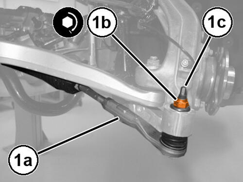
- Install the upper control arm ball joint into the knuckle and install a NEW upper control arm to knuckle pinch bolt, Do not tighten at this time.
- Install the lower control arm ball joint into the knuckle and install a NEW lower control arm to knuckle mounting nut, Do not tighten at this time.
- Install the tension strut ball joint into the knuckle and install a NEW tension strut to knuckle mounting nut, Do not tighten at this time.
- Carefully install the wheel speed sensor into the knuckle and install and tighten the wheel speed sensor to knuckle mounting bolt to the proper specification. Refer to TORQUE SPECIFICATIONS .
- Position the active damping sensor with bracket in place and install the two active damping sensor bracket to knuckle mounting bolts and securely tighten.
- Install the wheel studs in the hub and bearing, Do not tighten.
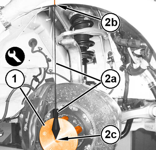
- Mount the special tool (special tool #2000025100, Measuring Tool, Wheel Centering) (1) on the wheel stud heads.
- Using an appropriate plump-bob (2a) determine and mark the stud curvature (2b) that corresponds to the wheel axle (2c).
- Position a suitable jack under the knuckle.
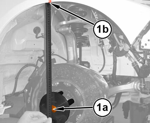
- Raise the knuckle up until the height 373.5 mm between the wheel center (1a) and the corresponding mark on the wheel arch (1b) is reached
- Tighten the upper control arm to knuckle pinch bolt to the proper specification. Refer to FRONT, TECHNICAL SPECIFICATIONS .
- Tighten the lower control arm to knuckle mounting nut to the proper specification. Refer to FRONT, TECHNICAL SPECIFICATIONS .
- Tighten the tension strut to knuckle mounting bolt to the proper specification. Refer to FRONT, TECHNICAL SPECIFICATIONS .
- Remove the jack from under the knuckle and remove the special tool and wheel studs from the hub and bearing.
- Install the outer tie rod end to the knuckle and install a NEW
outer tie rod end to knuckle mounting nut and tighten to the proper specification. Refer to TECHNICAL SPECIFICATIONS
.
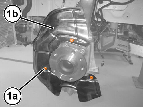
- Position the disc brake guard (1b), and install the three disc brake guard to knuckle mounting bolts (1a) and tighten to the proper specification. Refer to TORQUE SPECIFICATIONS .
- Install the front brake rotor. Refer to ROTOR, BRAKE, REMOVAL AND INSTALLATION .
- Remove the supports and lower the vehicle.
- Preform a wheel alignment. Refer to WHEEL ALIGNMENT, STANDARD PROCEDURE .