Bleeding Procedure Base
- Raise and support the vehicle. Refer to HOISTING, STANDARD PROCEDURE .
- With the ignition in the run position place the electric park brake in maintenance mode by selecting: menu, settings, driver assistance, auto park brake, off, brake service, yes. Then place the ignition in the off position.
- Disconnect and isolate the negative battery cable. If equipped with an Intelligent Battery Sensor (IBS), disconnect the IBS connector first before disconnecting the negative battery cable.
- Disconnecting the Electronic Control Module (ECM) wire harness connector.
- For vehicles with automatic transmission, to prevent the engine from being accidentally started only reconnect the battery after disconnecting the ECM wire harness connector.
- Remove all four wheels. Refer to REMOVAL AND INSTALLATION .
- Replace the fluid in the pressure bleeder with new fluid meeting the specifications in. Refer to CAPACITIES AND RECOMMENDED FLUIDS, SPECIFICATIONS
.
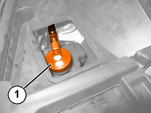
- Connect the pressure bleeder (1) to the brake fluid reservoir and pressurize the system.NOTE:
The pressure must be 29 - 43 psi during the first stage and second stage described below.
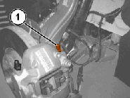
- Working at the right front caliper, position the brake fluid recovery hose to the INNER bleeder screw (1) and to the recovery container.
- Open the INNER bleeder screw (1) and without applying any pedal pressure on the system, allow a small amount of brake fluid to drain into the recovery container. Then tighten the bleeder screw and remove the recovery hose.
- Repeat the procedure on the left front caliper.
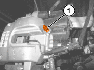
- Working at the right rear caliper, position the brake fluid recovery hose to the bleeder screw (1) and to the recovery container.
- Open the bleeder screw (1) and without applying any pedal pressure on the system, allow a small amount of brake fluid to drain into the recovery container. Then tighten the bleeder screw and remove the recovery hose.
- Repeat the procedure for the left rear caliper.
- Working at the left front caliper, position the brake fluid recovery hose to the INNER bleeder screw (1) and to the recovery container.
- Open the bleeder screw and slowly press the brake pedal down fully three or more times, until there are no more air bubbles in the recovery hose.
- Torque the bleeder screw to the proper specification. Refer to TORQUE SPECIFICATIONS .
- Repeat the bleed procedure on the OUTER bleeder screw of the left front caliper.
- Repeat the bleed procedure on the right front caliper.
- Working at the right rear caliper, position the brake fluid recovery hose to the bleeder screw (1) and to the recovery container.
- Open the bleeder screw allowing a small amount of brake fluid to drain into the recovery container. With the bleeder still open, have the assistant press the brake pedal three times and close the bleeder if the fluid is free from air.
- Tighten the bleeder screw (1) to the proper specification. Refer to TORQUE SPECIFICATIONS .
- Repeat the procedure for the left rear caliper.
- Connect the negative battery cable. If equipped with an Intelligent Battery Sensor (IBS), connect the IBS connector after connecting the negative battery cable.
- Connect a scan tool.
- Start the Replace Control Unit function, check for air in the hydraulic circuit between the control unit and the brake caliper.
- Check that the volumes of the Left Front, Right Front, Rear Right, and Left Rear shown on the scan tool are equal to or less than the maximum shown in the table.
Version 200 HP 280 HP Left front volume (mm3) 1440 - 2550 1495 - 2755 Right front volume (mm3) 1625 - 2735 1790 - 3050 Right rear volume (mm3) 870 - 1990 870 - 1990 Left rear volume (mm3) 855 - 1975 855 - 1975 - If any of the values shown in the table is higher than the reference threshold, repeat the bleeding procedure.
- If after repeating the bleeding procedure, the maximum values for the rear calipers are still higher than the limit values, proceed as follows:
- Identify which calipers are still out of range and remove them without disconnecting the hose.
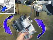
- Turn the brake caliper very slowly several times to the various possible positions, stop the motion and keep the bleeder screw pointing upwards for a few minutes.
- Install the brake caliper. Refer to CALIPER, DISC BRAKE, FRONT, REMOVAL AND INSTALLATION or CALIPER, DISC BRAKE, REAR, REMOVAL AND INSTALLATION .
- Repeat the bleeding procedure using the scan tool.
- For vehicles with automatic transmission, disconnect the battery and connect the ECM wire harness connectors.
- Connect the negative battery cable. If equipped with an Intelligent Battery Sensor (IBS), connect the IBS connector after connecting the negative battery cable.
- Remove the electric park brake from maintenance mode.
- Install all four wheels. Refer to REMOVAL AND INSTALLATION .
- Remove the support and lower the vehicle. Refer to HOISTING, STANDARD PROCEDURE .