Removal And Installation: Removal
NOTE:
If this Electronic Control Unit (ECU) is being replaced with a new unit, use a diagnostic scan tool to perform the Flash Programming Procedure (if available).
NOTE:
If the Integrated Control Unit (ICU) needs to be replaced, connect the diagnosis equipment to the vehicle diagnosis socket, go to "ABS control unit" in the "Miscellaneous functions" menu and start the following procedures:
- Longitudinal and lateral sensor calibration
- Pressure sensor calibration
- Steering angle sensor calibration.
- Electric Parking Brake (EPB) system assembly.
- Raise and support the vehicle. Refer to HOISTING, STANDARD PROCEDURE .
- Disconnect and isolate the negative battery cable.
- Remove the A/C suction line. Refer to LINE, A/C SUCTION, REMOVAL AND INSTALLATION Refer to, LINE, A/C SUCTION JUMPER, REMOVAL AND INSTALLATION .
- Remove the cowl panel. Refer to COVER, COWL PANEL, REMOVAL AND INSTALLATION
.NOTE:
Seal the unions that have been disconnected using suitable plugs to prevent moisture and impurities from entering the system.
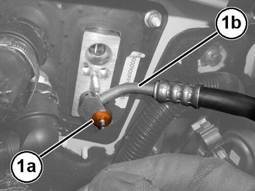
- Remove the mounting nut (1a) securing the A/C liquid line (1b) to the condenser.
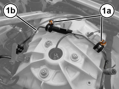
- Remove the mounting nuts (1a) and move to the side the A/C liquid line to the evaporator (1b).
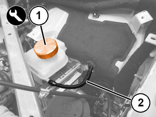
- Remove the brake fluid reservoir cap and install the (special tool #2000001400, Cap, Master Cylinder) (1) and tighten onto the brake fluid tank.
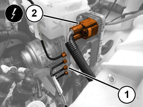
- Remove the brake tube nuts (1), from the ICU.
- Disconnect the electrical harness connector (2) at the ICU.
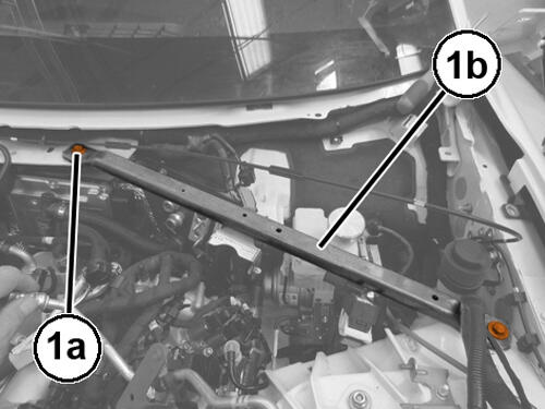
- Remove the mounting bolts (1a) and remove the body reinforcement (1b).
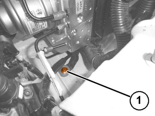
- Remove the mounting bolt (1) securing the ICU to the body.
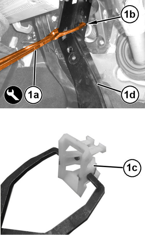
- Using (special tool #2000010500, Brake Switch Pliers) (1a) positioned on the rear part of the holes (1b) of the brake pedal, compress the retaining device (1c) and retract the brake pedal (1d) at the same time.NOTE:
The retaining device must be replaced each time the push rod is disconnected.
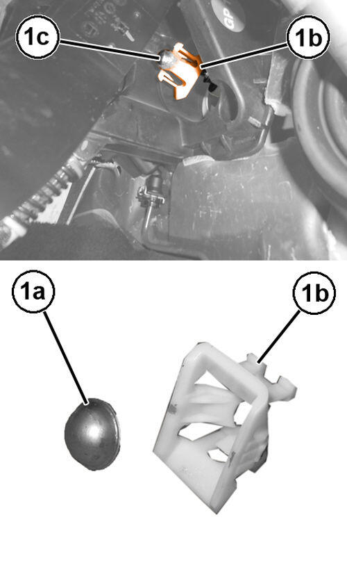
- Remove the cup (1a) and the retraining device (1b) from the push rod of the ICU (1c).
- Remove and DISCARD
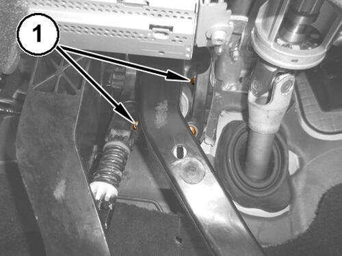
the ICU to the pedal unit support mounting nuts (1).
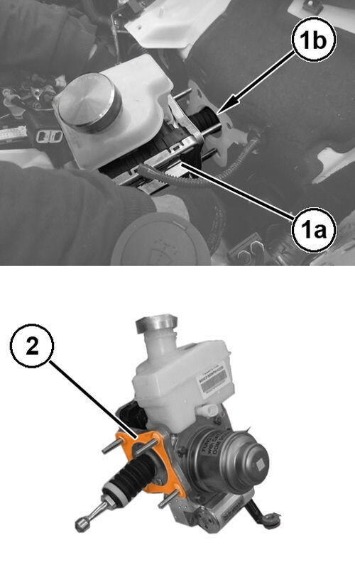
- Retract the ICU (1a) and remove the push rod (1b) from the front bulkhead.
- Remove and DISCARD the seal (2).