Removal And Installation: Installation
NOTE:
If this Electronic Control Unit (ECU) is being replaced with a new unit, use a diagnostic scan tool to perform the Flash Programming Procedure (if available).
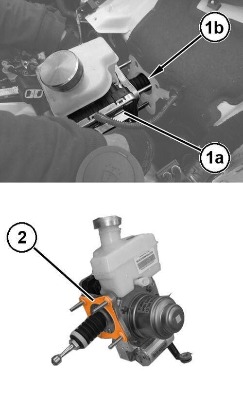
- Position the ICU in its housing with a NEW
seal (2) inserting the push rod through the front bulkhead (1b).
- Tighten the NEW
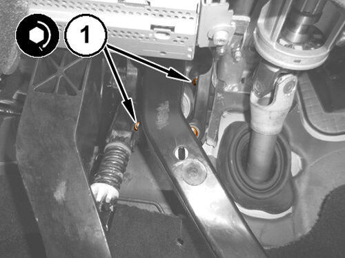
mounting nuts securing the ICU to the pedal unit to the proper specification. Refer to TORQUE SPECIFICATIONS
.NOTE:
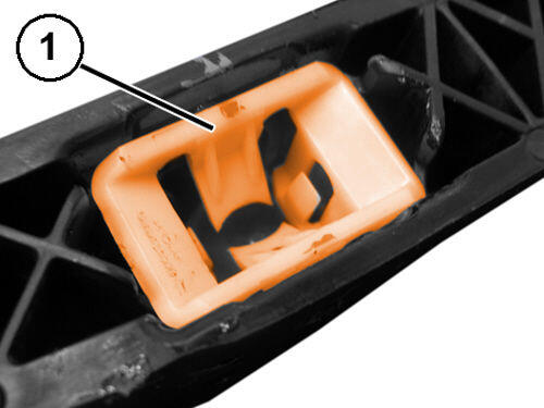
Position the cup before inserting the retaining device in the brake pedal.
- Position the cup.
- Insert the NEW retaining device in the brake pedal, engaging the side clips.
- Engage the brake pedal in the retaining device.
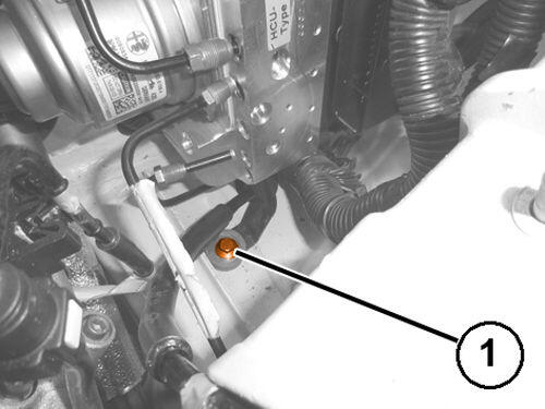
- Install the mounting bolts (1) securing the ICU to the body and tighten securely.
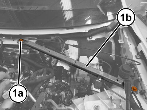
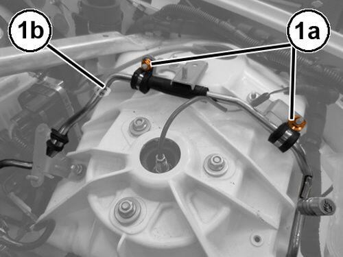
- Place the left body reinforcement (1b) in its housing and tighten the respective mounting bolts (1a) and tighten securely.
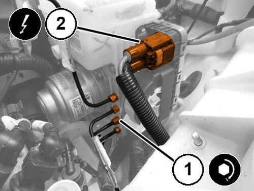
- Tighten the brake tube nuts on the ICU, to the proper specification. Refer to TORQUE SPECIFICATIONS .
- Connect the electrical harness connector (2) at the ICU.
- Position the a/c liquid line (1b) and tighten the mounting nuts (1a) to the proper specification. Refer to TECHNICAL SPECIFICATIONS
.NOTE:
Only use seal washers with an elastomer part in HNBR, resistant to R1234YF refrigerant.
The use of seal washers with another elastomer material may increase the risk of serious leaks of refrigerant from the air conditioning system.
- Install a NEW union O-ring.
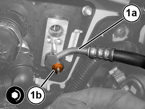
- Connect to the a/c suction line (1a) to the condenser and tighten the mounting nut (1b) to the proper specification. Refer to TECHNICAL SPECIFICATIONS .
- Install the cowl panel. Refer to COVER, COWL PANEL, REMOVAL AND INSTALLATION .
- Install the A/C suction line. Refer to LINE, A/C SUCTION, REMOVAL AND INSTALLATION Refer to, LINE, A/C SUCTION JUMPER, REMOVAL AND INSTALLATION .
- Bleed the brake system. Refer to STANDARD PROCEDURE .
- Connect the negative battery cable.
- Remove the supports and lower the vehicle.