Description And Operation: Operation
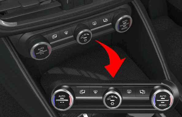
The vehicle is equipped with manual or automatic dual zone climate control system. With this type of climate control system, the driver and the front passenger can select the ideal temperature and choose how to direct the air flow. The air flow intensity will be the same on both sides because there is only one blower motor.
Automatic or manual operation can be chosen with the automatic climate control system. During automatic operation, the user simply needs to set a target temperature. The HVAC module determines the best combination of A/C compressor operation, blend door position, and outlet air direction and speed to control passenger compartment humidity and reach the target temperature.
During manual operation, the user can select A/C operation, air flow speed, air flow outlet location, and choose either fresh or recirculated air.
The HVAC module communicates on the Controller Area Network - Interior High Speed (CAN-IHS) and receives the information of the humidity sensor from the Instrument Panel Cluster (IPC) via a LIN serial bus.
The A/C activation request from the user and the heated rear window activation request are sent to the HVAC module via CAN to the Body Control Module (BCM). The A/C request status and the actuator position are stored in the HVAC module.
This system manages air recirculation, distribution and temperature using the actuators with potentiometer, for opening, closing and regulating the intermediate positions via electrical commands. Climate control system requests are shown on the multifunctional display (center of instrument panel). The HVAC module controls the outlet temperatures through the temperature sensors located in the climate control system.
The system manages the air temperature request by also controlling solar radiation through a sun sensor located on the instrument panel.
The HVAC acquires the temperature of the evaporator, via a NTC sensor, located in the air flowing through the evaporator, in order to manage the valve for external control of the variable displacement of the External Control Variable Displacement (ECVD) compressor.
The HVAC module receives a direct battery supply from the circuit protected by a fuse in the BCM, and receives an ignition-controlled supply (INT) from the circuit protected by a fuse in the BCM. The BCM has a dedicated ground.
The HVAC module is connected via the Controller Area Network (CAN) data bus to the BCM and to the other network modules.
Power, ground and the Local Interface Network (LIN) bus of the HVAC module are connected to the A/C Heater control.
The BCM receives direct battery power via the circuit protected by a maxi fuse on the Battery Distribution Unit (BDU). The BCM receives an ignition-controlled power supply (INT) from the Radio Frequency Hub Module (RFHM). The BCM has a duplicated reference ground.
The right lower outlet air temperature sensor, left lower outlet air temperature sensor, right upper outlet air temperature sensor and left upper outlet air temperature sensor are connected to the HVAC module. These sensors receive a reference ground from and send signals to the HVAC module.
The ambient air temperature sensor, which measures the outside temperature, is located in the passenger door mirror. The sensor is connected to the BCM and broadcasts the signal via CAN to the HVAC module.
A LIN bus connects the humidity sensor to the HVAC module and to the A/C Heater control. Ignition-operated power supply power (INT) is supplied to the humidity sensor from the circuit protected by a fuse in the BCM. The humidity sensor is also connected to ground.
The Air Quality Sensor (AQS) provides a control signal for recirculation when the outside air pollution index exceeds pre-set harmful levels. It is supplied ignition-control (INT) by the circuit protected by a fuse in the BCM and sends a signal to the HVAC module.
The sun sensor receives a reference ground from the HVAC module and sends two signals back to the HVAC module.
The in-car temperature sensor receives a reference ground from the HVAC module and sends two signals back to the HVAC module.
The evaporator temperature sensor receives a reference ground from the HVAC module and sends a signal back to the HVAC module.
All actuators are controlled by the HVAC module. They receive power and a reference ground to control the potentiometers from the HVAC module, and send a feedback signal to the HVAC module.
The blower motor is supplied a regulated voltage via the Power Blower Motor Module. The Power Blower Motor Module is supplied by a relay in the rear Power Distribution Center (PDC). The relay is supplied by a dedicated fuse in the rear PDC. The relay is controlled by an ignition-operated power supply - start-up excluded (INT/A) controlled by the BCM through the circuit protected by a fuse in the BCM. It receives commands for the various speeds from Power Blower Motor Module, the latter receives the Pulse Width Modulated (PWM) adjustment signal from the HVAC module and sends a feedback signal back to the HVAC module.