Removal And Installation: Removal
WARNING: This page is about a different variant/trim than selected.
- Disconnect and isolate the negative battery cable.
- Remove the hood. Refer to HOOD, REMOVAL AND INSTALLATION .
- Remove the front spoiler actuator
Refer to AIR DAM, FRONT, REMOVAL AND INSTALLATIONAIR DAM, FRONT CROSSMEMBER, REMOVAL AND INSTALLATION .
- Remove the radiator. Refer to RADIATOR, ENGINE COOLING, REMOVAL AND INSTALLATION .
- Remove the air dam front crossmember. Refer to AIR DAM, FRONT, REMOVAL AND INSTALLATIONAIR DAM, FRONT CROSSMEMBER, REMOVAL AND INSTALLATION .
- Remove the left side catalytic converter. Refer to CONVERTER, CATALYTIC, REMOVAL AND INSTALLATION .
- Remove the right side catalytic converter. Refer to CONVERTER, CATALYTIC, REMOVAL AND INSTALLATION .
- Remove the exhaust resonator. Refer to RESONATOR, EXHAUST, REMOVAL AND INSTALLATION .
- Remove the exhaust muffler. Refer to MUFFLER, EXHAUST, REMOVAL AND INSTALLATION .
- Remove the fuel tank heat shield. Refer to SHIELD, HEAT, REMOVAL AND INSTALLATION .
- Remove the front exhaust heat shield. Refer to SHIELD, HEAT, REMOVAL AND INSTALLATION .
- Remove the propeller shaft. Refer to REMOVAL AND INSTALLATION .
- Remove the right and left steering knuckle. Refer to KNUCKLE, STEERING, REMOVAL AND INSTALLATION .
- Remove the right and left front struts. Refer to STRUT, SUSPENSION, ASSEMBLY, REMOVAL AND INSTALLATION .
- Remove the front fuel vapor line. Refer to LINES, FUEL VAPOR, REMOVAL AND INSTALLATION .
- Remove the right fuel vapor line between fuel vapor solenoid and the intake manifold. Refer to LINES, FUEL VAPOR, REMOVAL AND INSTALLATION .
- Remove the left fuel vapor line between fuel vapor solenoid and the intake manifold. Refer to LINES, FUEL VAPOR, REMOVAL AND INSTALLATION .
- Remove the charge air water cooler support bracket. Refer to COOLER AND HOSES, CHARGE AIR, REMOVAL AND INSTALLATION .
- Remove the front fuel delivery line. Refer to LINES, FUEL, REMOVAL AND INSTALLATION .
- Remove the cowl panel cover. Refer to COVER, COWL PANEL, REMOVAL AND INSTALLATION
.
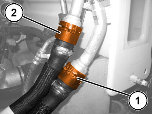
- Disconnect the quick connector (2) of the supercharger air cooling system feed pipe.
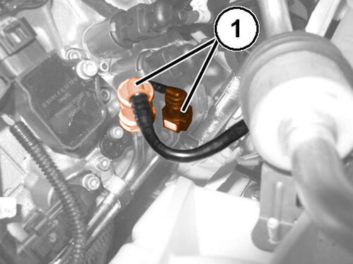
- Disconnect the quick connector (1) of the coolant supply pipe to the additional engine coolant radiator.
- Disconnect the quick connector of the coolant outlet pipe from the additional engine coolant radiator.
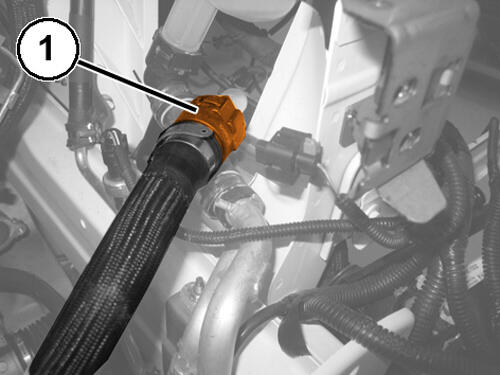
- Disconnect the engine cooling system supply hose quick connector (1).
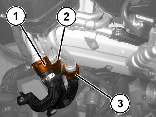
- Disconnect the quick connector of the coolant supply hose (2) to the supercharger air cooling system additional radiator.
- Disconnect the quick connector of the coolant return hose (3) from the supercharger air cooling system additional radiator.
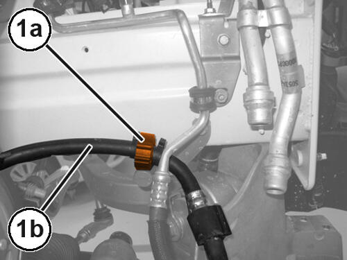
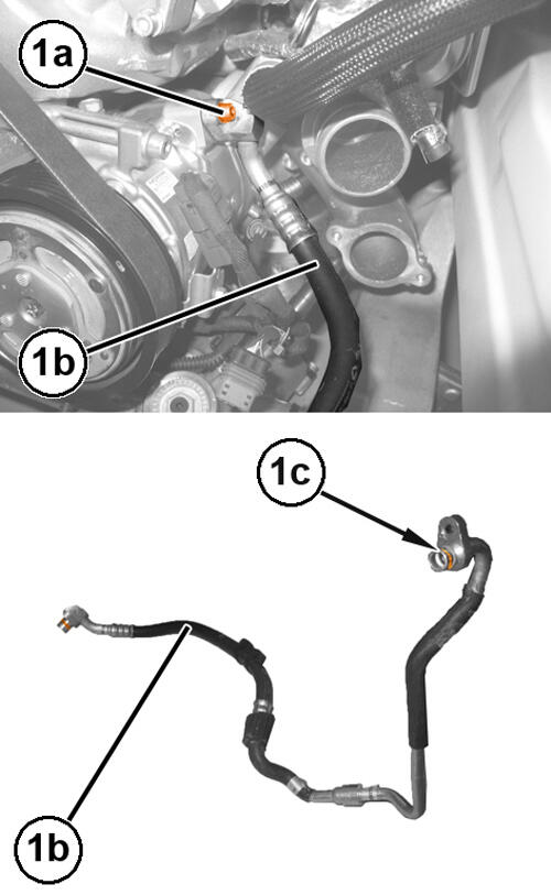
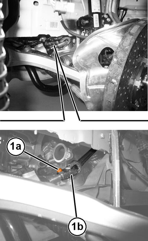
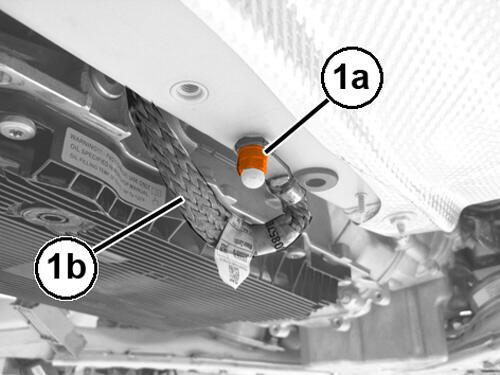
- Open the clip (1a) and release the lines (1b) from the air conditioning system compressor condenser.NOTE:
Seal the connectors that have been disconnected using suitable plugs to prevent dampness and impurities from entering the system.
- Remove the bolt (1a) and the line (1b) from the air conditioning system compressor condenser, complete with O-ring (1c).NOTE:
Seal the connectors that have been disconnected using suitable plugs to prevent dampness and impurities from entering the system.
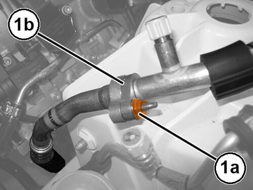
- Remove the nut (1a) and disconnect the intermediate connector (1b) for the line from the expansion valve to the air conditioning system compressor.
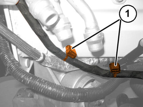
- Release the body wiring retaining clips (1).
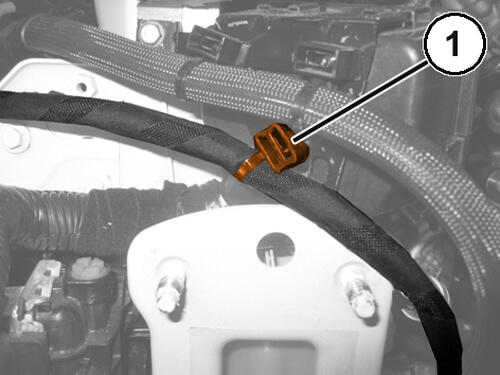
- Release the body wiring retaining clip (1).
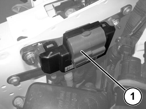
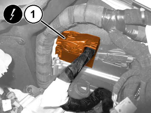
- Remove the terminal block cover (1).
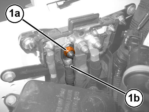
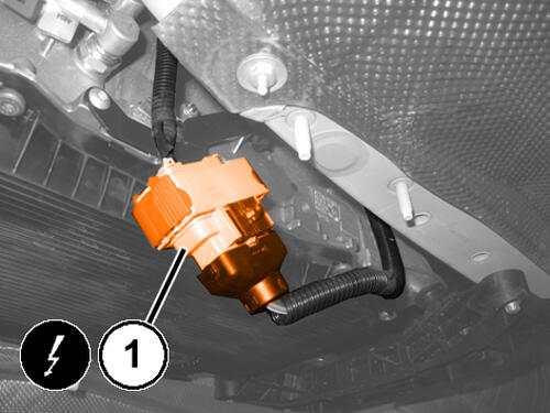
- Remove the nut (1a), disconnect the starter supply lead (1b) and secure it to the engine.
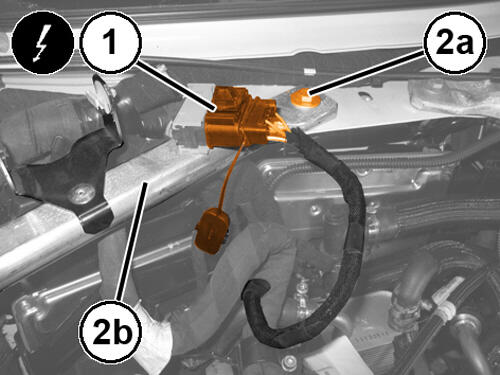
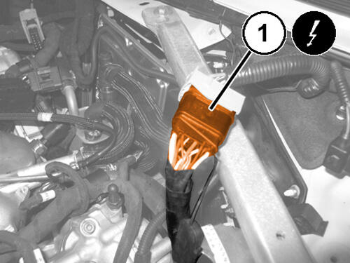
- Disconnect the front engine wire harness connector (1).
- Remove the bolt (2a) securing the body reinforcement (2b).
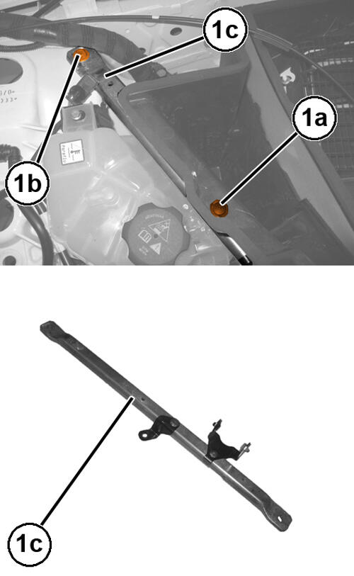
- Release the button (1a), remove the bolts (1b) and the body reinforcement (1c).
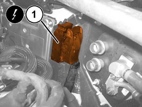
- Disconnect the Powertrain Control Module (PCM) wire harness connector (1).
- Disconnect the front engine wire harness connector (1).
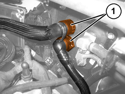
- Disconnect the quick couplings (1) for the heater water delivery and return hoses.
- Disconnect the Powertrain Control Module wire harness connector (1).
- Disconnect the quick connectors (1) for the vacuum lines.
- Release the wiring retaining clip.
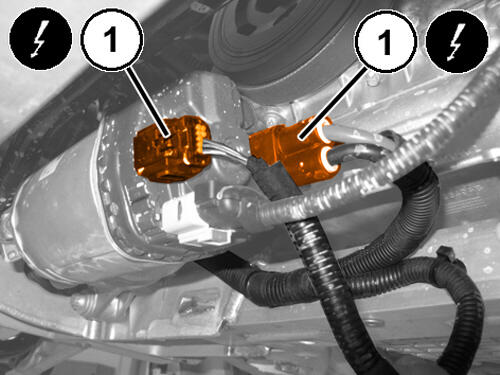
- Disconnect the steering gear wire harness connectors (1).NOTE:
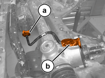
Never disconnect the electrical connections between the Electric Power Steering (EPS) module (a) and the steering box pinion (b).
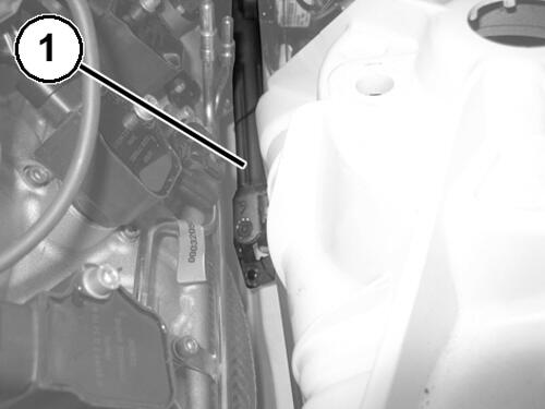
- Remove the bolt (1a) and disconnect the telescopic steering column (1b) from the steering box.
- Retract the telescopic steering column and secure it appropriately to the body.
- Release and disconnect the automatic transmission wiring harness connector (1).
- Remove the nut (1a) and disconnect the ground strap (1b).
- Place commercially available rubber spacer blocks, such as ROTFJ2427/J2440 or equivalent, on the (special tool #BX50-CHR, Table, Bishamon Lift) and position it under the powertrain and suspension crossmember assembly.
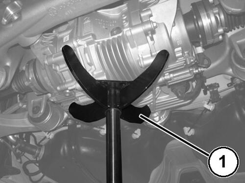
- Place a suitable hydraulic lift (1) under the rear differential to prevent the car from pitching.
- Remove the bolts (1) securing the gearbox mounting to the body.
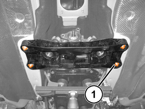
- Remove the front bolts securing the suspension crossmember to the body.
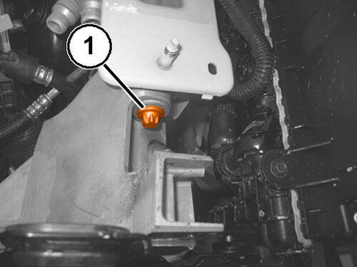
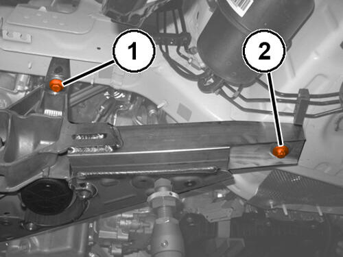
- Remove the central bolts (1) securing the suspension crossmember to the body.
- Remove the rear bolts (2) securing the suspension crossmember to the body.
- Lower the platform lift complete with powertrain assembly and suspension crossmember.