Removal And Installation: Right
WARNING: This page is about a different variant/trim than selected.
REMOVAL
- Remove the right timing chain and sprocket. Refer to CHAIN AND SPROCKETS, TIMING, REMOVAL AND INSTALLATION .
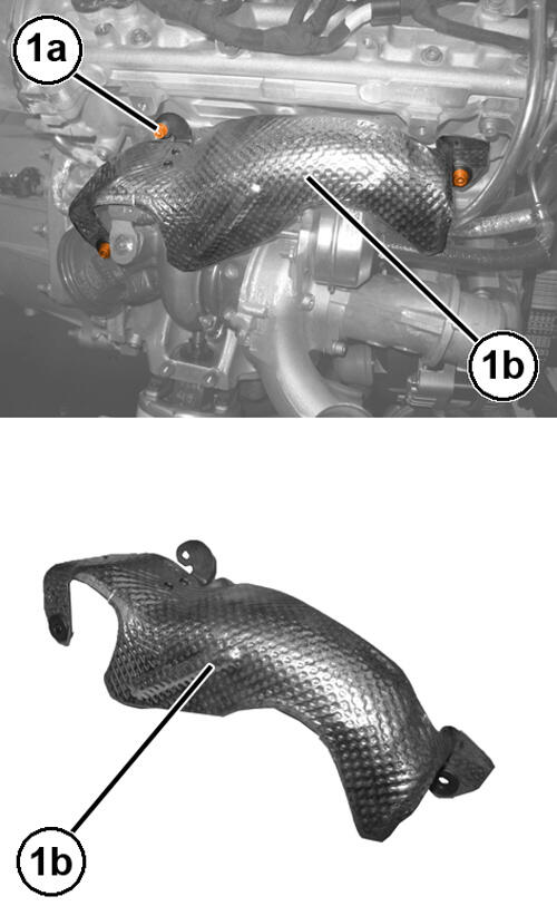
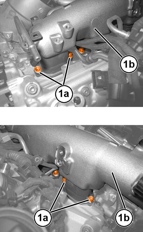
- Remove the bolts (1a) and the turbocharger heat shield (1b).
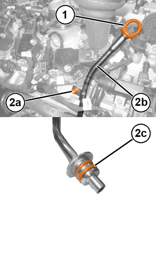
- Remove the engine oil dipstick (1).
- Remove the bolt (2a) and the engine oil dipstick pipe (2b) from the block, complete with O-rings (2c).
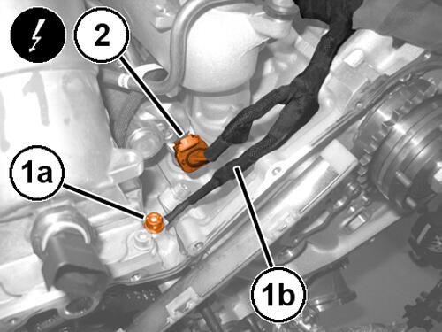
- Remove the bolt (1a) securing the ground wire (1b).
- Disconnect the fuel injector No. 3 wire harness connector (2).
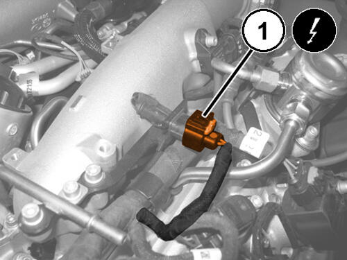
- Disconnect the knock sensor wire harness connector (1).
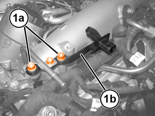
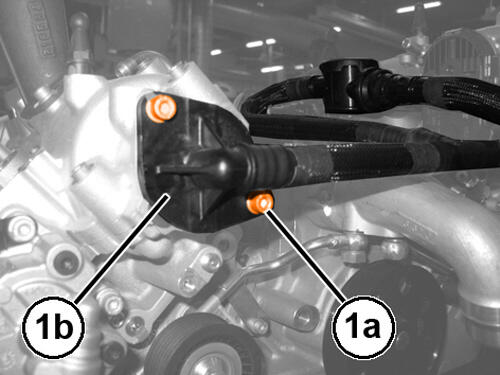
- Remove the bolts (1a) and the bracket (1b) complete with low pressure fuel pipe aside.
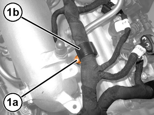
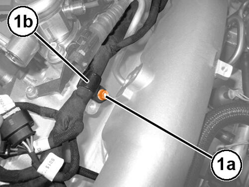
- Remove the bolt (1a) and disengage the wiring retaining collar (1b).
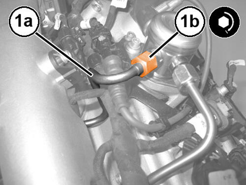
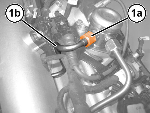
- Remove the connector (1a) securing the low pressure fuel tube (1b).
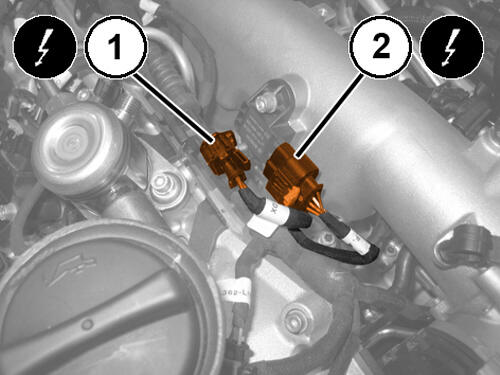
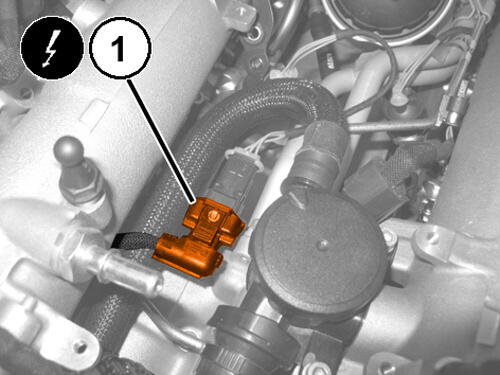
- Disconnect the fuel pump pressure regulator wire harness connector (1).
- Disconnect the air temperature and pressure sensor wire harness connector (2).
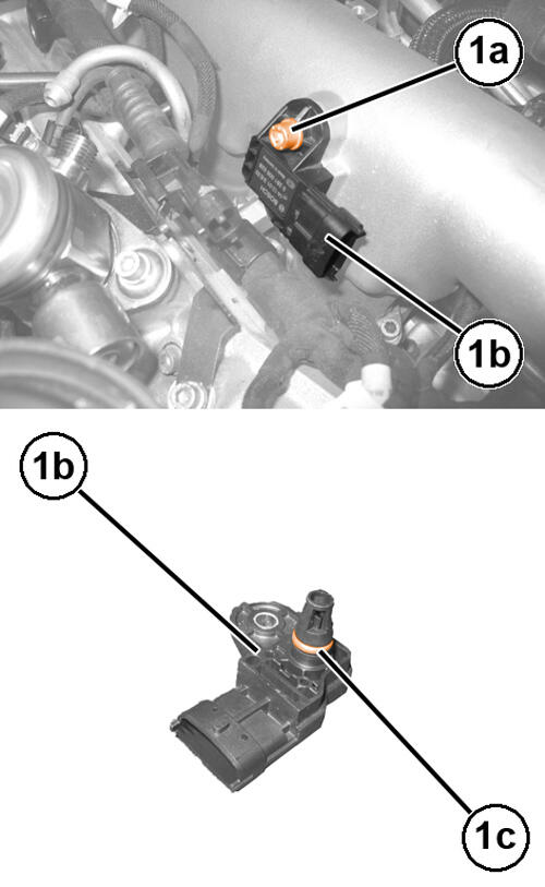
- Remove the bolt (1a) and the air temperature and pressure sensor (1b) complete with O-ring (1c).
- Remove the bolt (1a) fixing the wiring retaining collar (1b).
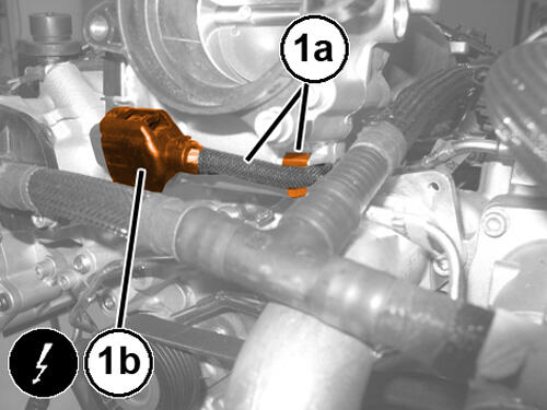
- Disengage the wiring from the retaining clip (1a) and disconnect the throttle body wire harness connector (1b).
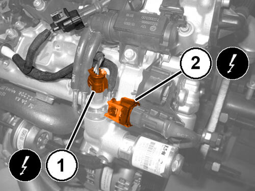
- Disconnect the right turbocharger lubrication deactivation circuit oil pressure sensor wire harness connector (1).
- Disconnect the right turbocharger lubrication deactivation circuit solenoid valve wire harness connector (2).
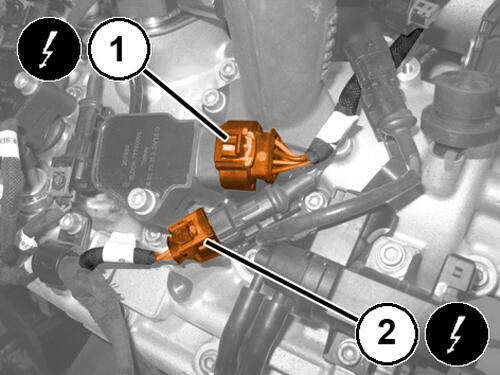
- Disconnect the wastegate solenoid valve wire harness connector (1).
- Disconnect the deactivation solenoid valve of cylinder 1 wire harness connector (2), intake side.
- Disconnect the ignition coil of cylinder 1 wire harness connector (1).
- Disconnect the deactivation solenoid valve of cylinder 1 wire harness connector (2), exhaust side.
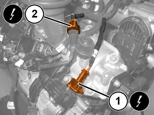
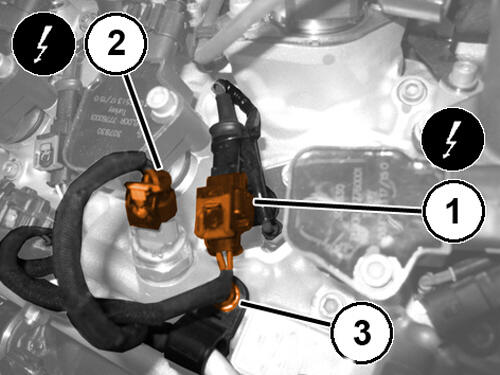
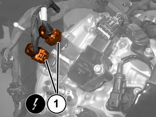
- Disconnect the deactivation solenoid valve of cylinders 2 - 3 wire harness connector (1), exhaust side.
- Disconnect the right cylinder head tappets deactivation circuit engine oil pressure sensor wire harness connector (2).
- Remove the bolt securing the wiring retaining collar (3).
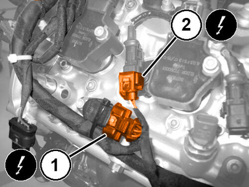
- Disconnect the Camshaft Position (CMP) sensor wire harness connector (1), exhaust side.
- Disconnect the deactivation solenoid valve of cylinders 2 - 3 wire harness connector (2), intake side.
- Disconnect the CMP sensor wire harness connector (1), intake side.
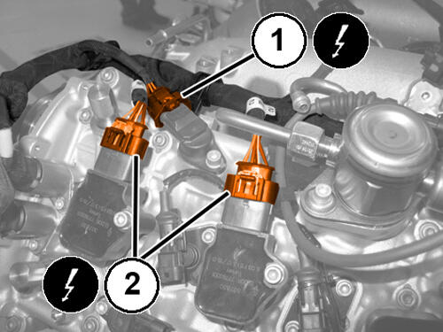
- Disconnect the ignition coils of cylinders 2 - 3 wire harness connector (2).
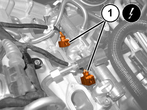
- Disconnect the Variable Valve Timing (VVT) solenoid wire harness connectors (1).
- Disconnect the fuel pressure sensor wire harness connector (1).
- Remove the bolts (1a) and the intake manifold (1b).
- Remove the gasket.
- Disconnect the fuel injectors 1 - 2 wire harness connector (1).NOTE:
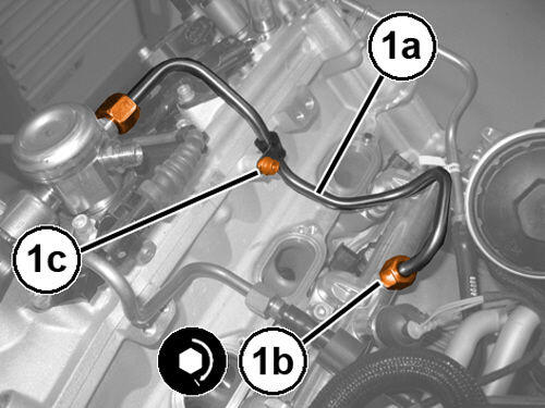
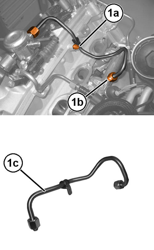
The high pressure fuel pipe must always be replaced every time it is removed.
- Remove the bolt (1a), the connectors (1b), and the high pressure fuel pipe (1c).
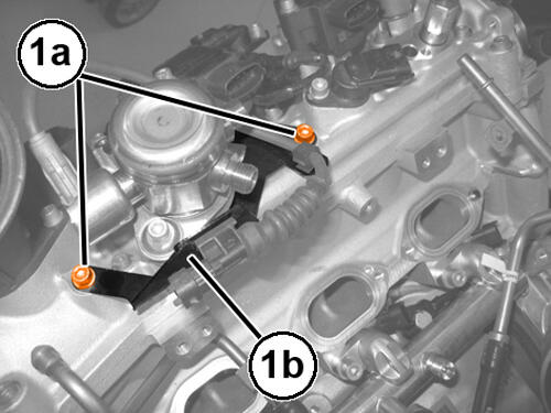
- Remove the bolts (1a) securing the pressure pump (1b) wiring retaining bracket.NOTE:
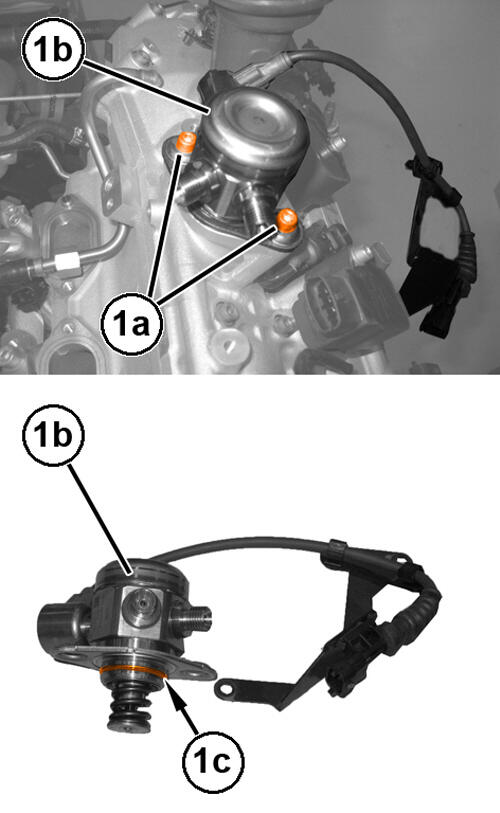
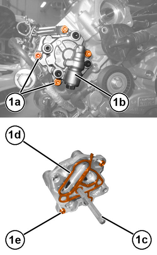
Handle the pressure pump with care because accidental knocks could compromise its operation.
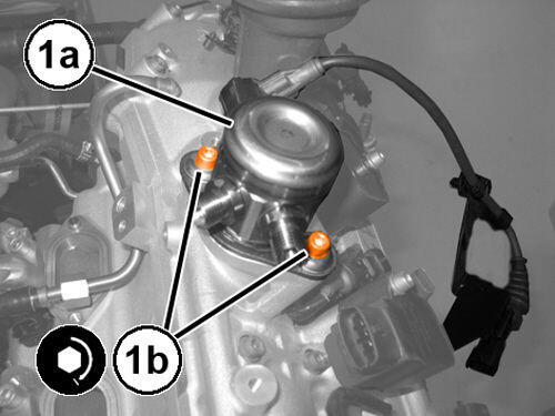
- Remove the bolts (1a) and the pressure pump (1b) complete with wiring retaining bracket and O-ring (1c).
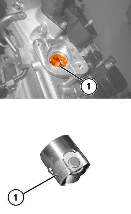
- Remove the roller tappet (1).
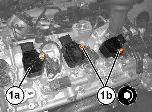
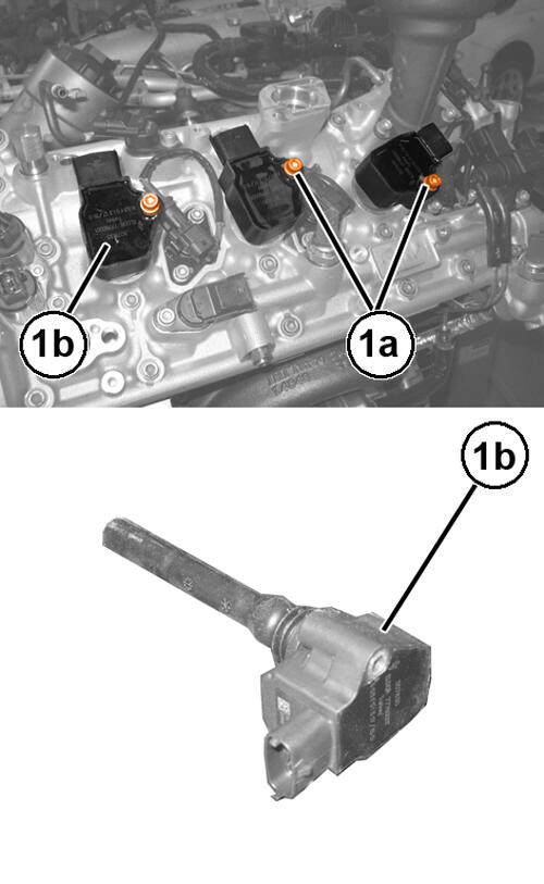
- Remove the bolts (1a) and the ignition coils (1b).
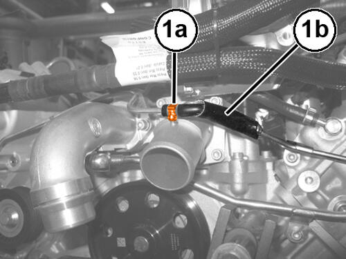
- Loosen the clamp (1a) and disconnect the air vacuum hose (1b).
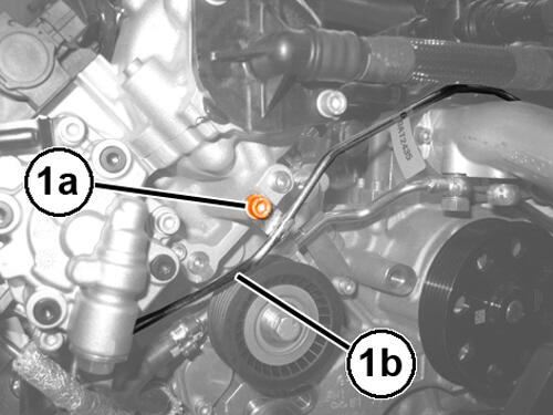
- Remove the air vacuum hose middle retaining bracket (1b) bolt (1a).
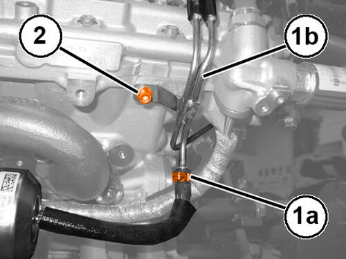
- Loosen the clamp (1a) and disconnect the turbocharger actuator (1b) air vacuum hose.
- Remove the air vacuum hose retaining bracket bolt (2).
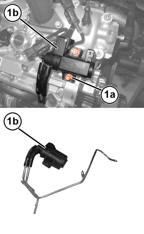
- Remove the bolts (1a) and the wastegate solenoid valve (1b) complete with pipes.
- Remove the bolts (1a) and disengage the flange (1b) securing the deactivation solenoid valve of cylinders 2 - 3, intake side.
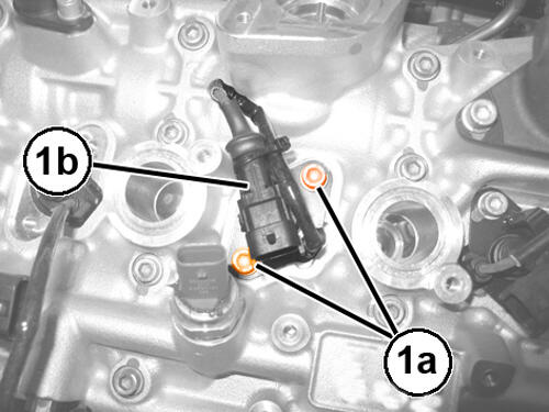
- Remove the bolts (1a) and disengage the flange (1b) securing the deactivation solenoid valve of cylinders 2 - 3, exhaust side.
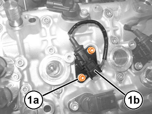
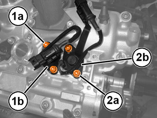
- Remove the bolts (1a) and the flange (1b) securing the deactivation solenoid valve of cylinder 1, exhaust side.
- Remove the bolts (2a) and the flange (2b) securing the deactivation solenoid valve of cylinder 1, intake side.
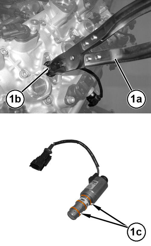
- Using a suitable tool (1a), remove the deactivation solenoid valve of cylinders 2 - 3 (1b), intake side, complete with O-rings (1c).
- Proceed in the same way to remove the remaining deactivation solenoid valves.
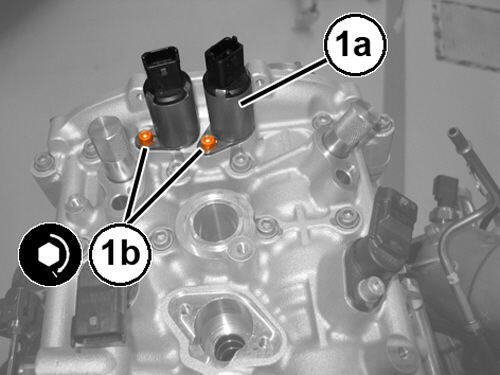
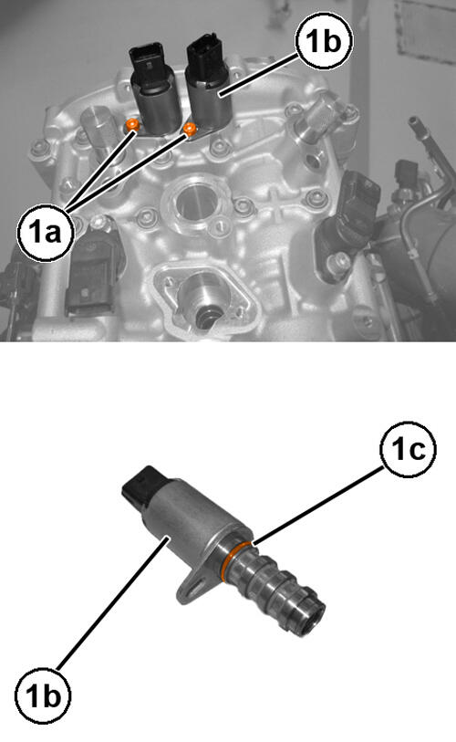
- Remove the bolt (1a) and the VVT solenoids (1b) complete with O-rings (1c).
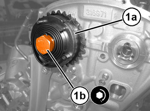
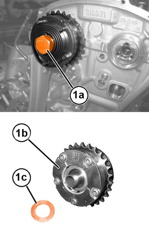
- Remove the left-handed bolt (1a) and the intake side variator (1b) complete with washer (1c).
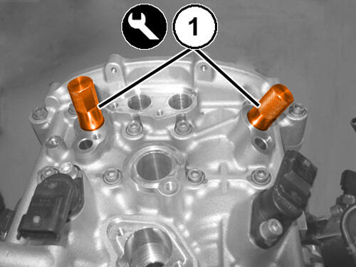
- Remove the (special tool #2024000090, Guide Pins, Camshaft) (1).
- Remove the bolts (1a) and disconnect the engine oil vapor recovery pipe (1b) complete with O-ring.
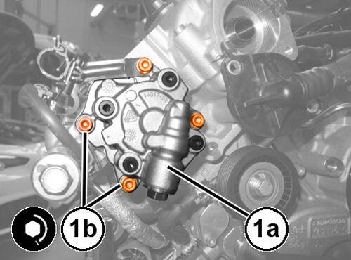
- Remove the bolts (1a) and the right cylinder head tappets deactivation circuit oil pump (1b), complete with shaft (1c), gasket (1d) and centering dowels (1e).
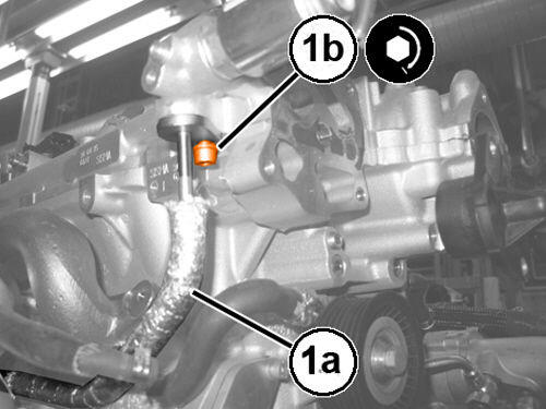
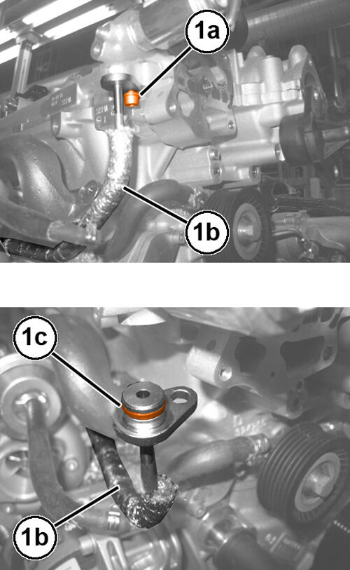
- Remove the bolt (1a) and disconnect oil delivery pipe to the turbocharger (1b), complete with O-ring (1c).
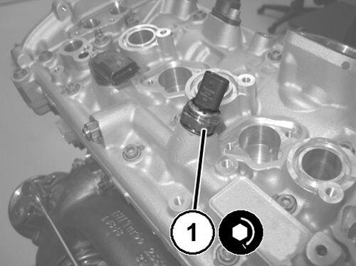
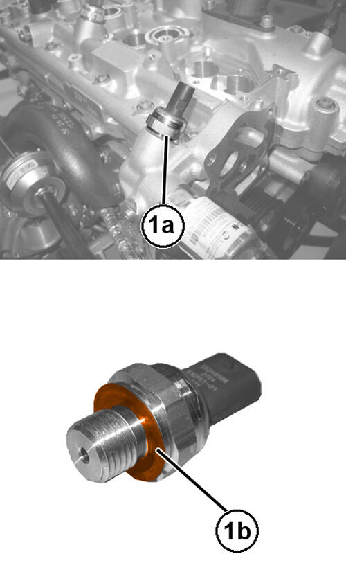
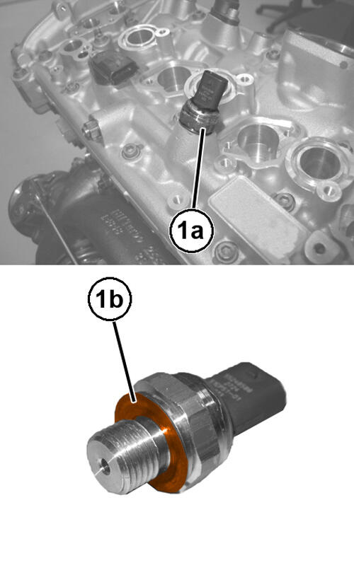
- Remove the right turbocharger lubrication deactivation circuit engine oil pressure sensor (1a) and sealing washer (1b).
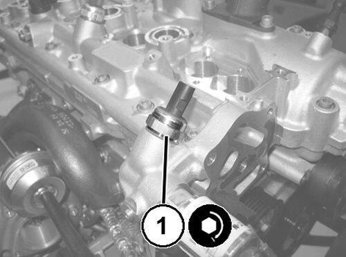
- Remove the right cylinder head tappets deactivation circuit engine oil pressure sensor (1a) and sealing washer (1b).
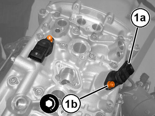
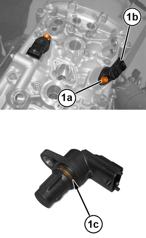
- Remove the bolt (1a) and CMP sensors (1b) complete with O-rings (1c).
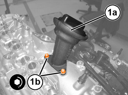
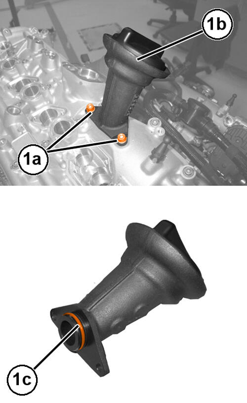
- Remove the bolts (1a) and the engine oil filler (1b) complete with O-ring (1c).
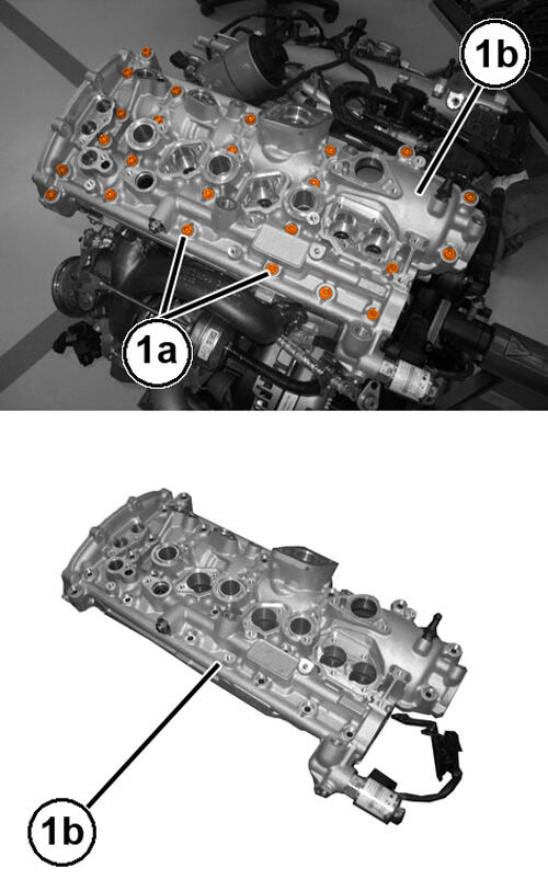
- Remove the bolts (1a) and the cylinder head cover (1b).
- Remove the cylinder head cover gasket (1).
- Remove the engine oil pipe middle seal (2).
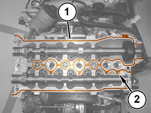
INSTALLATION
- Install NEW gasket, inserting them in the special grooves in the cylinder head.
- Install the NEW
engine oil duct O-rings, inserting them in the grooves provided in the cylinder head.
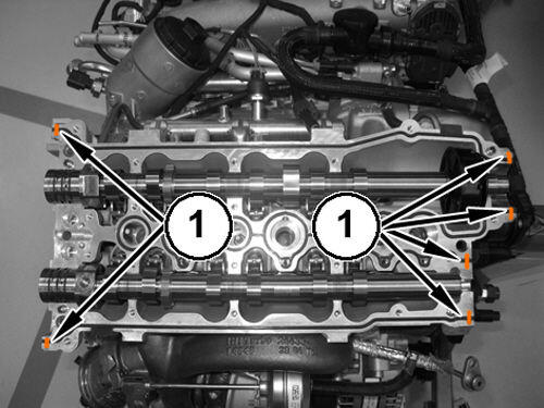
- Apply a 2 +/- 0.5 mm bead of Dow Corning® sealant in the places shown in illustration (1).
- Install the cylinder head cover and tighten the bolts finger tight.
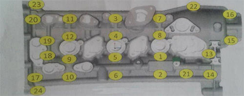
- Using the tightening sequence shown in illustration, tighten the bolts to the proper specification. Refer to TORQUE SPECIFICATIONS
.
- Using a NEW
O-ring, install the engine oil filler (1a) and tighten the bolts (1b) to the proper specification. Refer to LUBRICATION
.
- Using a NEW
O-ring, install the Camshaft Position (CMP) sensors (1a), and tighten the screws (1b) to the proper specification. Refer to TORQUE SPECIFICATIONS
.
- Using a NEW
gasket, install the right cylinder head tappets deactivation circuit engine oil pressure sensor and tighten to the proper specification. Refer to TORQUE SPECIFICATIONS
.
- Using a NEW
gasket, install the right turbocharger lubrication deactivation circuit engine oil pressure sensor and tighten to the proper specification. Refer to TURBOCHARGER
.
- Using a NEW
O-ring, install the oil pipe to the turbocharger (1a) and tighten the bolt (1b) to the proper specification. Refer to TURBOCHARGER
.
- Using a NEW
gasket and centering dowels, Install the right cylinder head (1a) tappets deactivation circuit oil pump and tighten the bolts (1b) to the proper specification. Refer to TORQUE SPECIFICATIONS
.NOTE:
Lubricate the screw (1b) with engine oil before tightening it.
- Using a NEW washer and NEW left-handed bolt (1b), install the intake side variator (1a) and tighten the NEW bolt (1b) to the proper specification. Refer to TORQUE SPECIFICATIONS .
- Using a NEW
O-ring, install the engine oil vapor recovery tube and securely tighten the bolts.
- Using a NEW O-ring, install the Variable Valve Timing (VVT) solenoids (1a) and tighten the bolts (1b) to the proper specification. Refer to TORQUE SPECIFICATIONS .
- Using a NEW O-ring, install the intake side deactivation solenoid valve of cylinders 2 - 3.
- Install the deactivation solenoid valve flange and securely tighten the bolts.
- Proceed in the same way to install the remaining deactivation solenoid valves.
- Install the wastegate solenoid valve complete with tubes, and securely tighten the bolts.
- Connect the air vacuum hoses and tighten the bands.
- Securely tighten the air vacuum tube bolts.
- Install the ignition coils (1a) and tighten the bolts (1b) to the proper specification. Refer to TORQUE SPECIFICATIONS .
- Install the roller tappet.
- Using a NEW
O-ring, install the pressure pump (1a) complete with the wiring retaining bracket and tighten the bolts (1b) to the proper specification. Refer to TORQUE SPECIFICATIONS
.
- Install the NEW high pressure fuel pipe (1a) and tighten the connector (1b) and the bolt of the middle bracket (1c) to the proper specification. Refer to TORQUE SPECIFICATIONS .
- Connect the fuel injectors 1 - 2 wire harness connector.
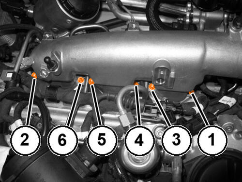
- Using a NEW gasket, install the intake manifold and tighten the bolts finger tight.
- Using the tightening sequence shown in illustration, tighten the bolts to the proper specification. Refer to TORQUE SPECIFICATIONS .
- Connect the fuel pressure sensor wire harness connector.
- Connect the VVT solenoids wire harness connectors.
- Connect the wire harness connector for cylinders 2 - 3 ignition coils.
- Connect the CMP sensor wire harness connector, intake side.
- Connect the deactivation solenoid valve of cylinders 2 - 3 wire harness connector, intake side.
- Connect the CMP sensor wire harness connector, exhaust side.
- Tighten the bolt securing the wiring retaining collar.
- Connect the right cylinder head tappets deactivation circuit engine oil pressure sensor wire harness connector.
- Connect the deactivation solenoid valve of cylinders 2 - 3 wire harness connector, exhaust side.
- Connect the deactivation solenoid valve of cylinder 1 wire harness connector, exhaust side.
- Connect the ignition coil for cylinder 1 wire harness connector.
- Connect the deactivation solenoid valve of cylinder 1 wire harness connector, intake side.
- Connect the wastegate solenoid valve wire harness connector.
- Connect the right turbocharger lubrication deactivation circuit solenoid valve wire harness connector.
- Connect the right turbocharger lubrication deactivation circuit oil pressure sensor wire harness connector.
- Connect the throttle body wire harness connector and engage the wiring with the retaining clips.
- Tighten the wiring retaining collar bolt.
- Using a NEW O-ring, install the air temperature and pressure sensor and securely tighten the bolt.
- Connect the air temperature and pressure sensor wire harness connector.
- Connect the fuel pump pressure regulator wire harness connector.
- Install the low pressure fuel tube (1a) and tighten the connector (1b) to the proper specification. Refer to TORQUE SPECIFICATIONS .
- Engage the retaining collar wiring and securely tighten the bolt.
- Install the bracket complete with low pressure fuel tube and securely tighten the bolts.
- Connect the knock sensor wire harness connector.
- Connect the fuel injector 3 wire harness connector.
- Install the ground wire and securely tighten the bolt.
- Using a NEW O-rings, install the engine oil dipstick tube and securely tighten the bolts.
- Install the engine oil dipstick.
- Install the turbocharger heat shield and securely tighten the bolts.
- Install the right timing chain and sprocket. Refer to CHAIN AND SPROCKETS, TIMING, REMOVAL AND INSTALLATION .