Description And Operation: Description
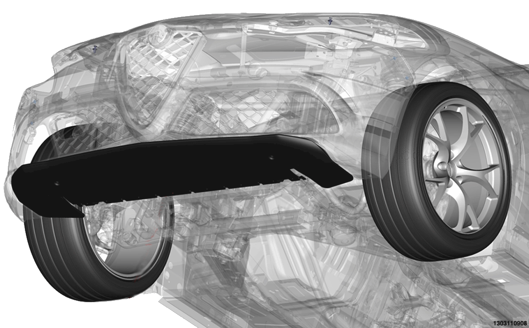
The Quadrifoglio version has an aerodynamic air dam in the bottom part of the front fascia.
The front aerodynamic air dam has the purpose of creating a deviation of air flow that is channelled into the under-body area of the vehicle with the purpose of increasing grip and the aerodynamic load on the front.
The front air dam is activated only when the Dynamic or Race driving modes are selected. When other driving modes are selected, the air dam is not activated.
In Dynamic and Race modes, activation of the air dam occurs in the range of speed between 62 mph and 142 mph (100 km/h and 230 km/h). Outside of said speed range, the air dam is always closed.
In order to avoid continuous movements of opening and closing of the air dam in the case where the vehicle speed oscillates around the limit values of the range of speed (100km/h and 230km/h), the CDCM module controls the air dam so that it does not open exactly at 100km/h
The opening of the air dam, beyond accentuating the Venturi effect, primarily allows shifting of the aerodynamic load toward the front bringing about a more responsive character to the vehicle. The shifting towards the front of the aerodynamic load is due to the deflection of the flow around the air dam that, in the open position, behaves like a reversed wing.
When the air dam is closed, most of the aerodynamic load is shifted towards the rear.
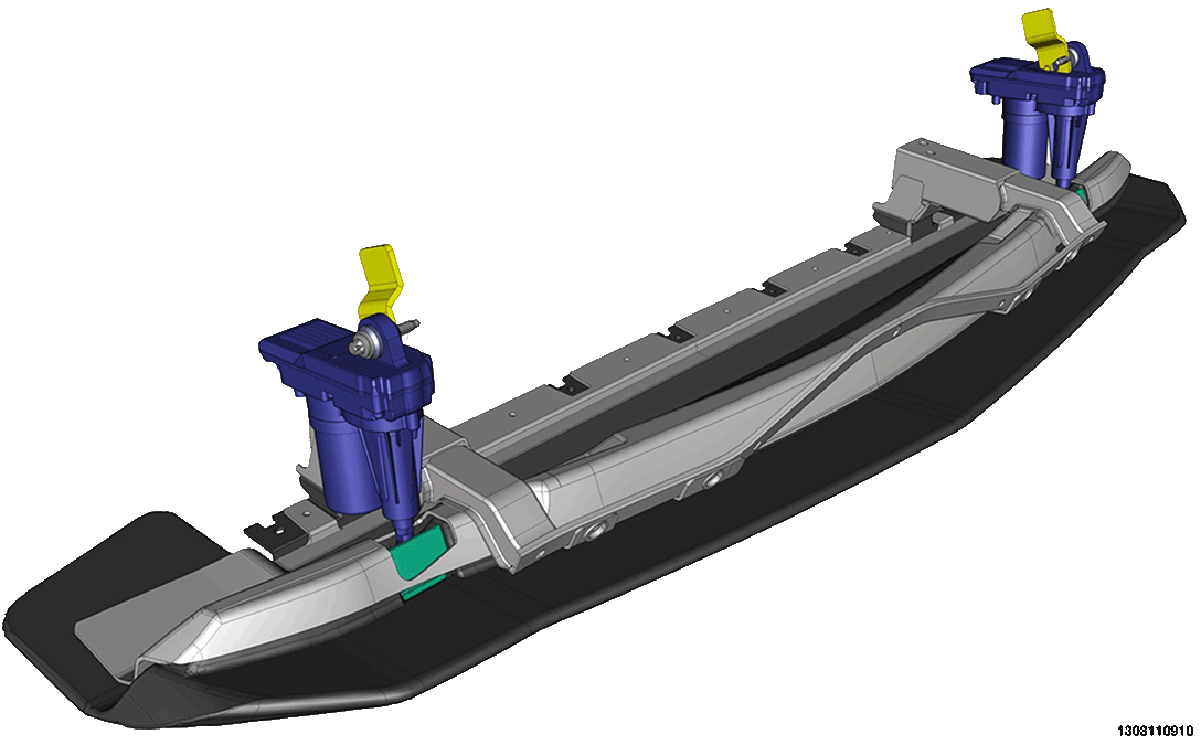
AIR DAM MECHANISM
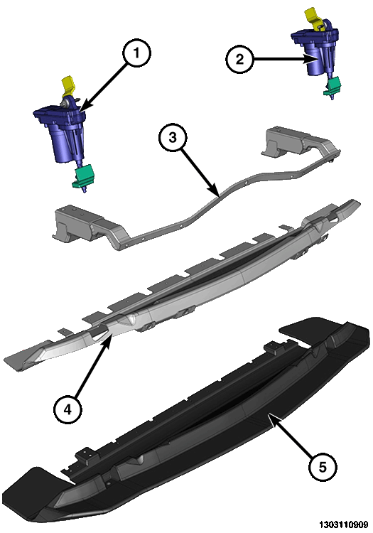
| 1. Right actuator |
| 2. Left actuator |
| 3. Transverse support |
| 4. Shell protection |
| 5. Front air dam made of carbon fiber |
The front air dam is piloted by two actuators. One is located in the right part of the deflector (Master actuator) and the other on the left side (Slave actuator).
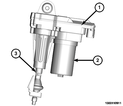
| 1. Electronic control unit |
| 2. Small brushless electric motor |
| 3. Handling stem |
Actuators
The right and left actuators, integrate an electronic data processing unit with the mechanical part. The electronic unit is equipped with a CAN interface, a microprocessor and position sensor which detect the small movement piston's vertical displacement. The mechanical part contains a small electric motor and a reduction gear assembly through which the small electric motor moves an irreversible trapezoidal screw. The right MASTER actuator receives movement commands from the car dynamics control module CDCM.