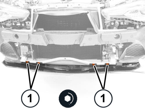
Removal And Installation: Removal
- Raise and support the vehicle. Refer to HOISTING, STANDARD PROCEDURE .
- Using a diagnostic scan tool, under miscellaneous functions perform the "Actuators Open Position Movement" function.
- Disconnect and isolate the negative battery cable.
- Remove the front engine belly pan. Refer to BELLY PAN, ENGINE, REMOVAL AND INSTALLATION .
- Remove the front fascia. Refer to FASCIA, FRONT, REMOVAL AND INSTALLATION .
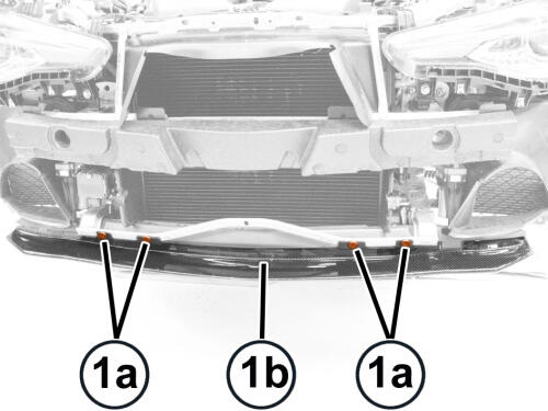
- Remove the front screws (1a) attaching the front air dam (1b).
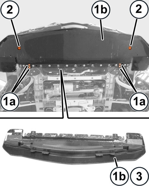
- Remove the lower screws (1a) for the front air dam (1b).
- Unscrew the air dam nuts from the actuator shanks (2).
- Remove the front air dam (1b).
INSTALLATION
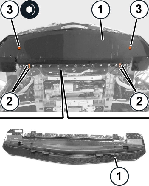
- Position the front air dam (1) onto the vehicle.
- Install the lower screws (2) and tighten to the proper specification. Refer to TECHNICAL SPECIFICATIONS .
- Tighten the actuator positioning nuts (3) to the proper specification. Refer to TECHNICAL SPECIFICATIONS .
- Tighten the front screws (1) to the proper specification. Refer to TECHNICAL SPECIFICATIONS .
- Install the fascia. Refer to FASCIA, FRONT, REMOVAL AND INSTALLATION .
- Refer to BELLY PAN, ENGINE, REMOVAL AND INSTALLATION or BELLY PAN, REAR, REMOVAL AND INSTALLATION or BELLY PAN, REAR SUSPENSION, REMOVAL AND INSTALLATION or BELLY PAN, SIDE, REMOVAL AND INSTALLATION .
- After installing and adjusting the front fascia, use the diagnostic scan tool to perform the active aerodynamic system self-learning procedure. The system will stop with the air dam in the raised position. At that point check the distance between the air dam and the bumper using the appropriate gauges. If the outcome of the check is negative check for foreign bodies between the mobile wing and the fixed parts, check for any actuator errors, adjust the actuator position values, fix the faults and clear any errors. Repeat the self-learning procedure and the check between the air dam and bumper. If the distance is still out of specification, the fascia must be adjusted again.