Removal - 2.9L
- Remove the front bumper reinforcement. Refer to REINFORCEMENT, BUMPER, FRONT, REMOVAL AND INSTALLATION .
- Remove the air dam crossmember. Refer to AIR DAM, FRONT, REMOVAL AND INSTALLATION or AIR DAM, FRONT CROSSMEMBER, REMOVAL AND INSTALLATION .
- Remove the radiator. Refer to RADIATOR, ENGINE COOLING, REMOVAL AND INSTALLATION .
- Remove the turbo charger heat exchangers. Refer to COOLER AND HOSES, CHARGE AIR, REMOVAL AND INSTALLATION .
- Remove the front steering knuckles. Refer to KNUCKLE, STEERING, REMOVAL AND INSTALLATION .
- Remove the front catalytic converters. Refer to CONVERTER, CATALYTIC, REMOVAL AND INSTALLATION
.
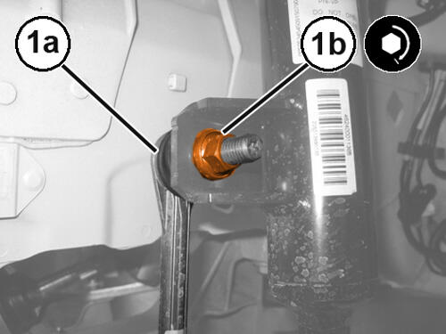
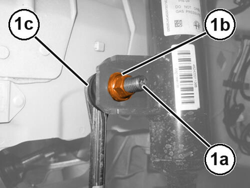
- Using a suitable wrench, hold the pin (1a), remove the nut (1b) and disconnect the stabilizer bar link (1c) from the shock absorber.
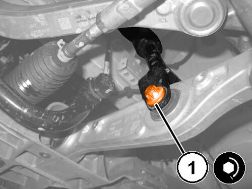
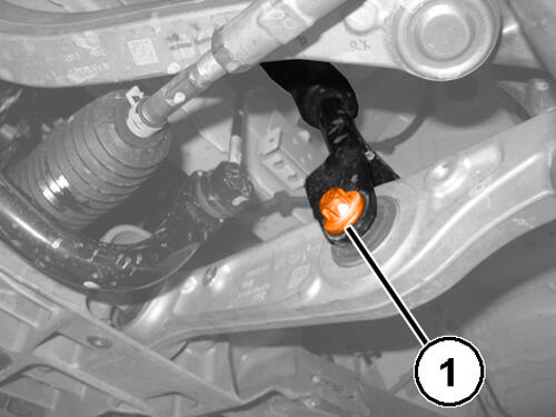
- Remove the bolt (1) securing the shock absorber fork to the control arm.
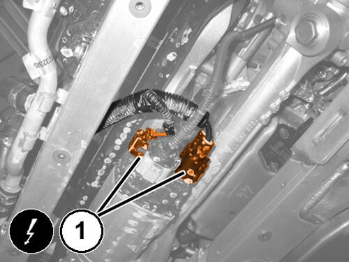
- Disconnect the wire harness connections (1) for the steering gear.
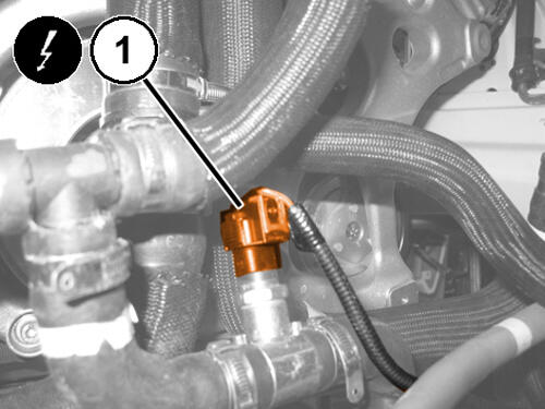
- Disconnect the wire harness connection (1) for the turbo air cooling system temperature sensor.
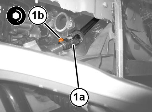
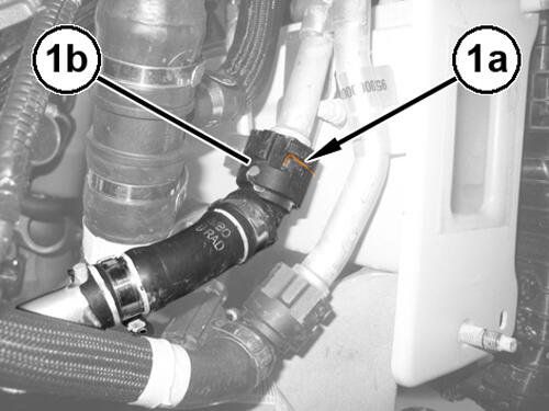
- Release the retaining clip (1a) and disconnect the quick coupling (1b) of the return water pipe from the additional engine coolant radiator.
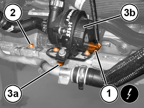
- Disconnect the wire harness connection (1) of the turbo air cooling system coolant electro-pump.
- Remove the bolt attaching the water supply line to the turbo air coolant radiator system to the crossmember.
- Remove the bolts (3a) and move the turbo air coolant system's water pump to one side (3b).
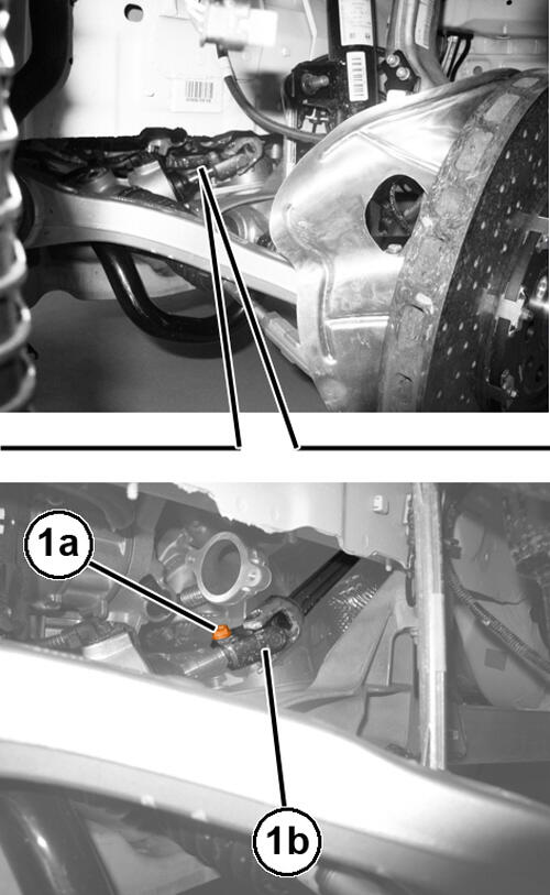
- Remove the bolt (1a) and disconnect the column (1b) from the steering gear.
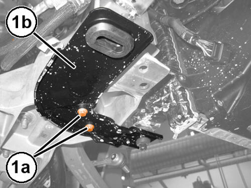
- Remove the bolts (1a) and remove the left radiator support bracket (1b).
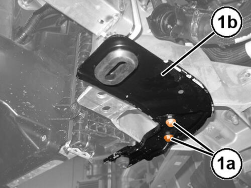
- Remove bolts (1a) and remove the right radiator support bracket (1b).
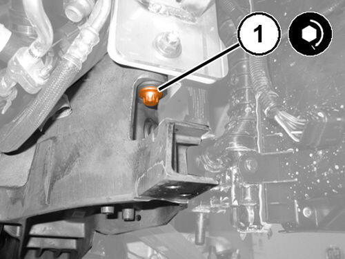
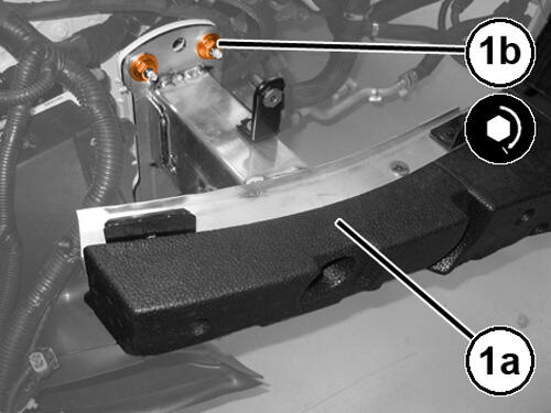
- Position the bumper reinforcement (1a) into place and tighten the nuts (1b) to the proper specification. Refer to TECHNICAL SPECIFICATIONS .
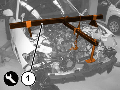
- Install the engine support tools 2000040436 or (special tool #8534C, Fixture, Driveline Support) (1).
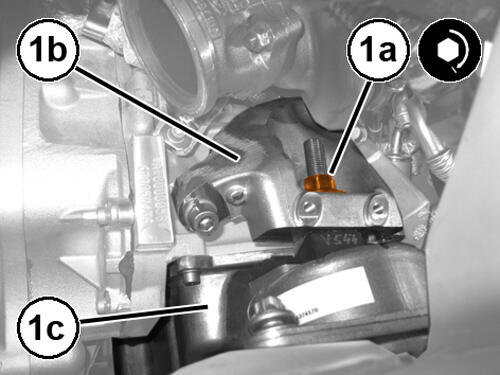
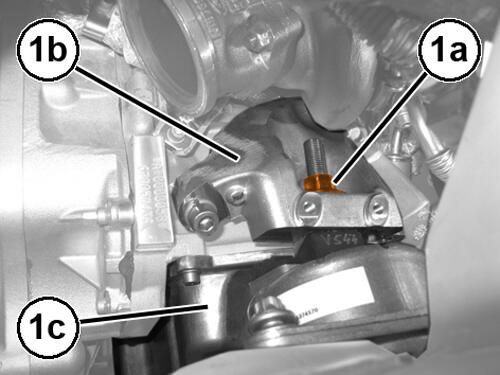
- On both sides, remove the nut (1a) fastening the engine mount (1b) to the mount housing (1c).
- Place commercially available rubber spacer blocks, such as ROTFJ2427/J2440 or equivalent, on the (special tool #BX50-CHR, Table, Bishamon Lift) and position it under the crossmember assembly.
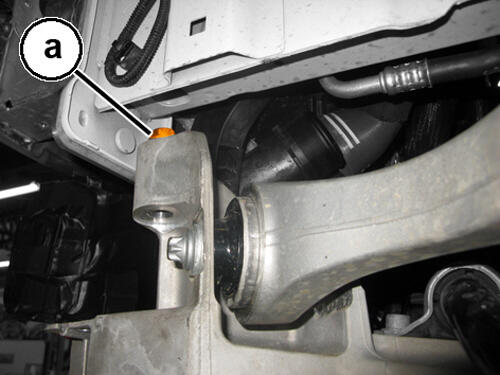
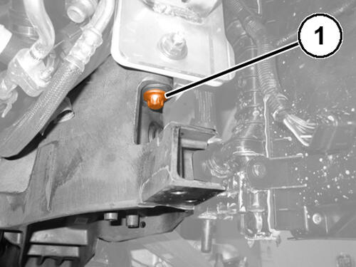
- Working on both sides, remove the front bolts attaching the front suspension crossmember to the body.
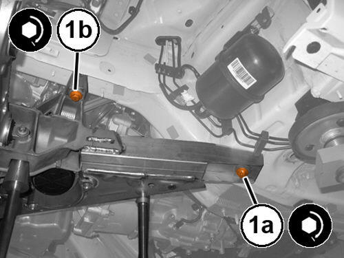
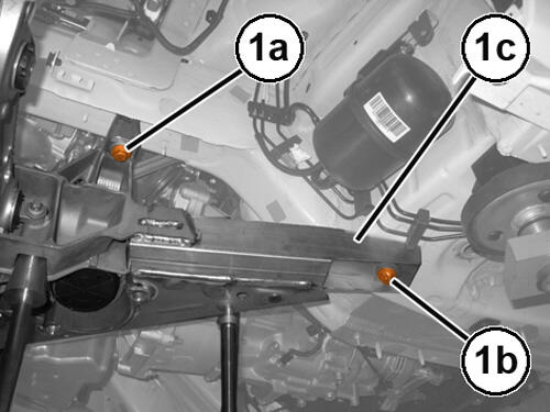
- Operating on both sides, remove the bolts (1a), (1b) and remove the suspension crossmember (1c).
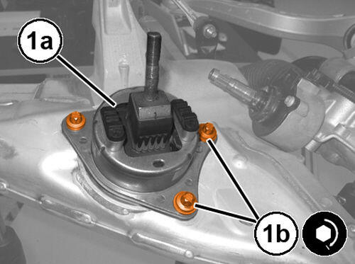
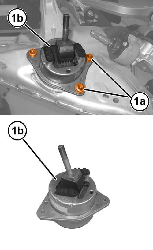
- Working on both sides, remove the bolts (1a) and remove the engine mount (1b) from the crossmember.
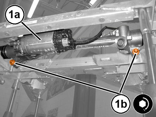
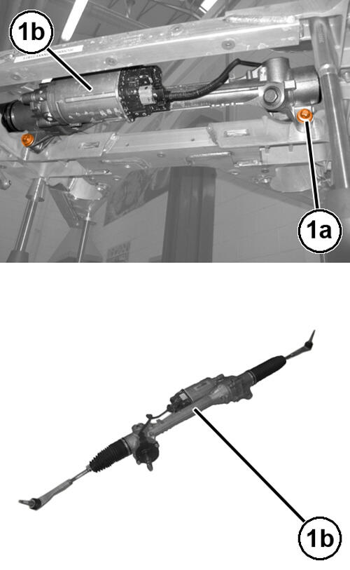
- Remove bolts (1a) and remove steering gear (1b) from the crossmember.
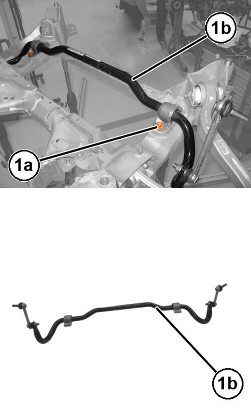
- Remove the bolts (1a) and remove the stabilizer bar (1b) from the crossmember.
NOTE:
Position the steering wheel spokes in a the straight ahead position.
NOTE:
Avoid rotating the steering column until the steering column has been reconnected once again to the steering gear.
INSTALLATION
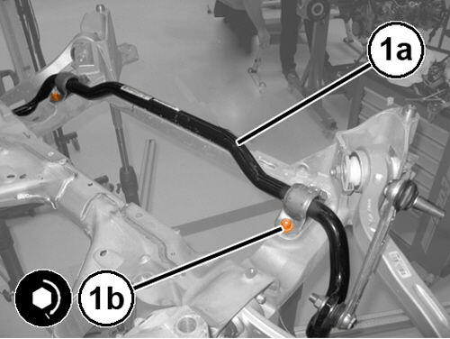
- Position the stabilizer bar (1a) in its housing and tighten the bolts (1b) to the proper specification. Refer to FRONT, TECHNICAL SPECIFICATIONS
.
- Install the steering gear (1a) and tighten the bolts (1b) to the proper specification. Refer to TECHNICAL SPECIFICATIONS
.
- On both sides, place the isolators in their seats (1a) and tighten the bolts (1b) to the proper specification. Refer to TORQUE SPECIFICATIONS .
- Lift the suspension crossmember into place using the (special tool #BX50-CHR, Table, Bishamon Lift).
- On both sides, tighten the new bolts (1a) and (1b) to the proper specification. Refer to TECHNICAL SPECIFICATIONS .
- Working on both sides, tighten the new front bolts attaching the suspension crossmember to the proper specification. Refer to TECHNICAL SPECIFICATIONS .
- Remove the equipment used for supporting the front suspension crossmember.
- On both sides, tighten the nut (1a) fastening the bracket (1b) to the isolator (1c) to the proper specification. Refer to TORQUE SPECIFICATIONS .
- Remove the tools used for supporting the engine.
- Place the radiator left mounting bracket in its housing and tighten the bolts. Proceed in the same way for the right side.
- Connect the steering column (1a) to the steering box pinion and tighten the new bolt (1b) to the proper specification. Refer to TECHNICAL SPECIFICATIONS
.
- Refit the turbo air coolant system water pump in its seat and tighten the attaching bolts (3a) for the suspension crossmember to the proper specification. Refer to TORQUE SPECIFICATIONS GAS ENGINE .
- Refit the turbo air coolant system water pump pipe in its seat and tighten the attaching bolt (2) for the suspension crossmember to the proper specification. Refer to TORQUE SPECIFICATIONS GAS ENGINE .
- Connect the wire harness connector (1) of the turbo air cooling system coolant electro-pump.
- Connect the quick connector (1b) of the coolant inlet pipe to the additional engine coolant radiator (1a).
- Connect the wire harness connector (1) for the turbo air cooling system temperature sensor.
- Connect the wire harness connectors (1) for the steering gear.
- Connect the shock absorber fork to the lower rear wishbone and tighten the new attaching bolt (1) to the proper specification. Refer to TECHNICAL SPECIFICATIONS
.
- Connect the left stabilizer bar (1a) joint to the shock absorber and tighten the new nut (1b) to the proper specification. Refer to TECHNICAL SPECIFICATIONS .
- Install the front catalytic converters. Refer to CONVERTER, CATALYTIC, REMOVAL AND INSTALLATION .
- Install the front steering knuckles. Refer to KNUCKLE, STEERING, REMOVAL AND INSTALLATION .
- Install the turbo charger heat exchangers. Refer to COOLER AND HOSES, CHARGE AIR, REMOVAL AND INSTALLATION .
- Install the radiator. Refer to RADIATOR, ENGINE COOLING, REMOVAL AND INSTALLATION .
- Install the air dam crossmember. Refer to AIR DAM, FRONT, REMOVAL AND INSTALLATION or AIR DAM, FRONT CROSSMEMBER, REMOVAL AND INSTALLATION .