Removal - 2.0L
- Raise and support the vehicle. Refer to HOISTING, STANDARD PROCEDURE .
- Remove the front steering knuckles. Refer to KNUCKLE, STEERING, REMOVAL AND INSTALLATION .
- Remove the front catalytic converters. Refer to CONVERTER, CATALYTIC, REMOVAL AND INSTALLATION .
- Remove the engine cover. Refer to COVER, ENGINE, REMOVAL AND INSTALLATION
.
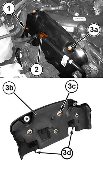
- Open the retaining clip and release the fuel line.
- Open the retaining clip and release the fuel vapor line (2).
- Remove the bolts (3a) and remove the turbocharger air cooling system cover (3b), releasing the retaining pins (3c) from the flexible mounts.
- Remove the air filter housing. Refer to BODY, AIR CLEANER, REMOVAL AND INSTALLATION
.
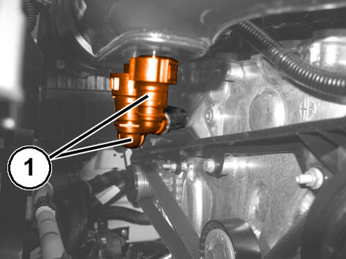
- Disconnect the quick couplings (1) from the unions of the turbocharger air intake line.
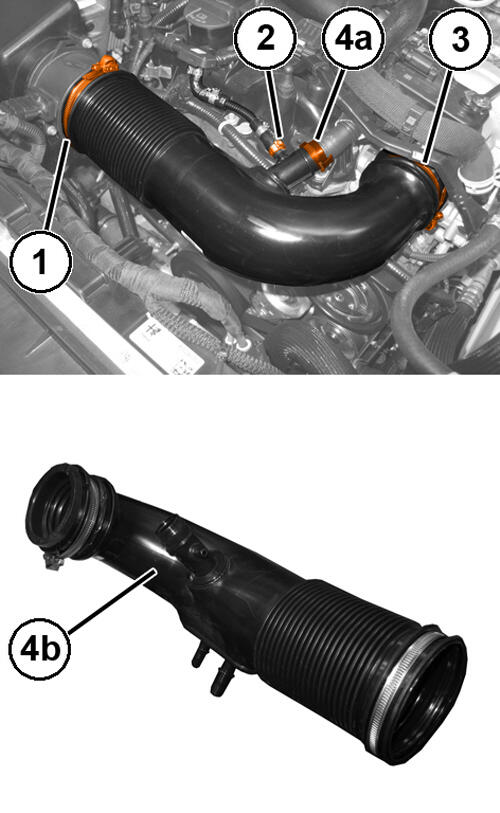
- Loosen the clamp (1) and disconnect the air line from the air flow meter.
- Loosen the clamp (2) and disconnect the engine oil vapor intake line from the air line.
- Loosen the clamp (3) attaching the air intake line to the turbocharger.
- Disconnect the engine oil vapor outlet line (4a) quick coupling and remove the turbocharger air intake line (4b).
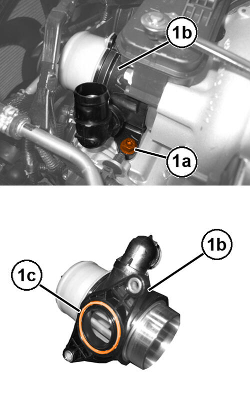
- Remove the bolts (1a) and remove the intake air line to the turbocharger (1b) complete with gasket (1c).
- Remove the front fascia. Refer to FASCIA, FRONT, REMOVAL AND INSTALLATION .
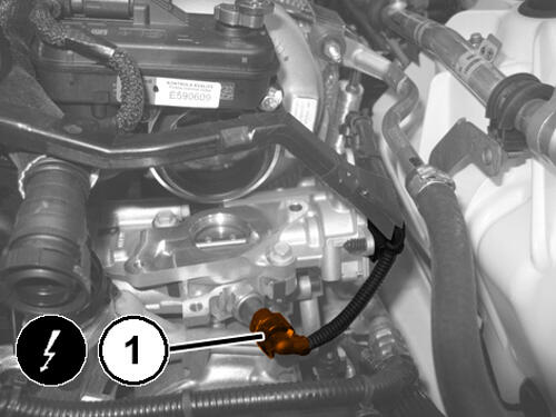
- Disconnect the wire harness connector (1) of the low pressure EGR exhaust gas temperature sensor.
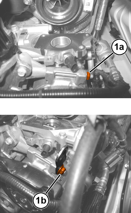
- Remove the nut (1a) fastening the air conditioning compressor and refit the bracket (1b) that supports the powertrain.
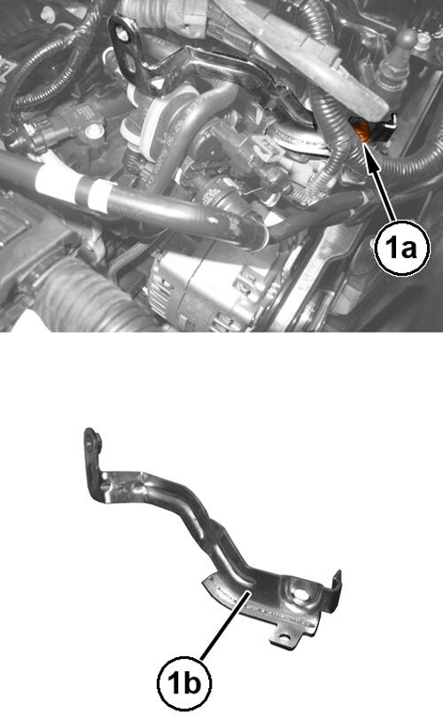
- Remove the bolts (1a) and remove the heat shield mounting bracket (1b).
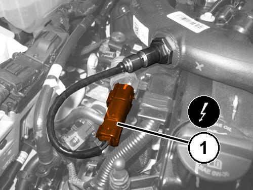
- Disconnect the wire harness connector (1) for the oxygen sensor.
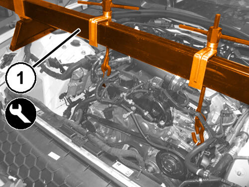
- Fit the bracket (1) for supporting the powertrain assembly.
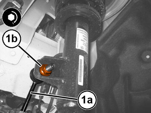
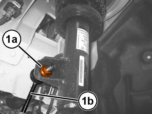
- On both sides, remove the nut (1a) and disconnect the stabilizer bar (1b) joint from the shock absorber.
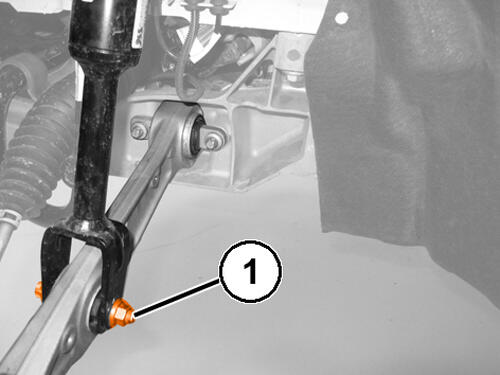
- On both sides, remove the bolt (1) fastening the shock absorber to the rear lower control arm.
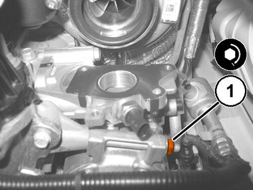
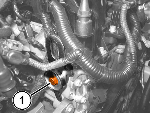
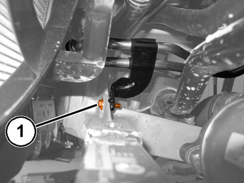
- Remove the bolt (1) and release the automatic transmission fluid supply and return line.
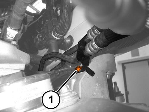
- Remove the bolt (1) and release the automatic transmission fluid supply and return line.
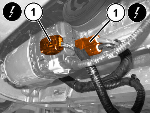
- Disconnect the steering gear wire harness connectors (1).
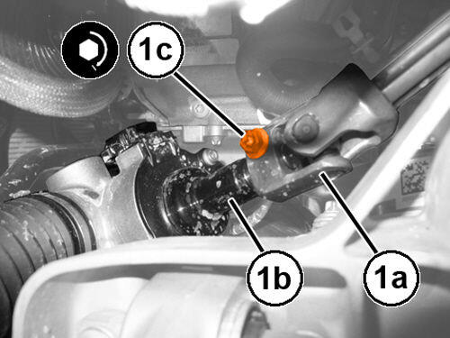
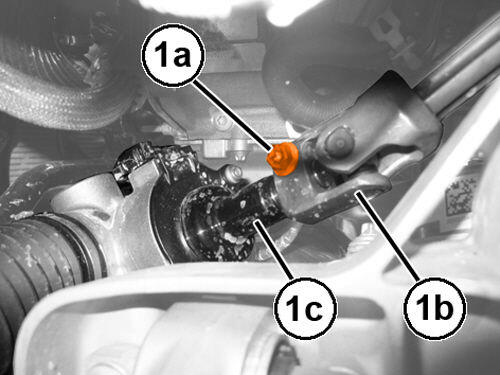
- Remove the bolt (1a) and disconnect the column (1b) from the steering gear (1c).
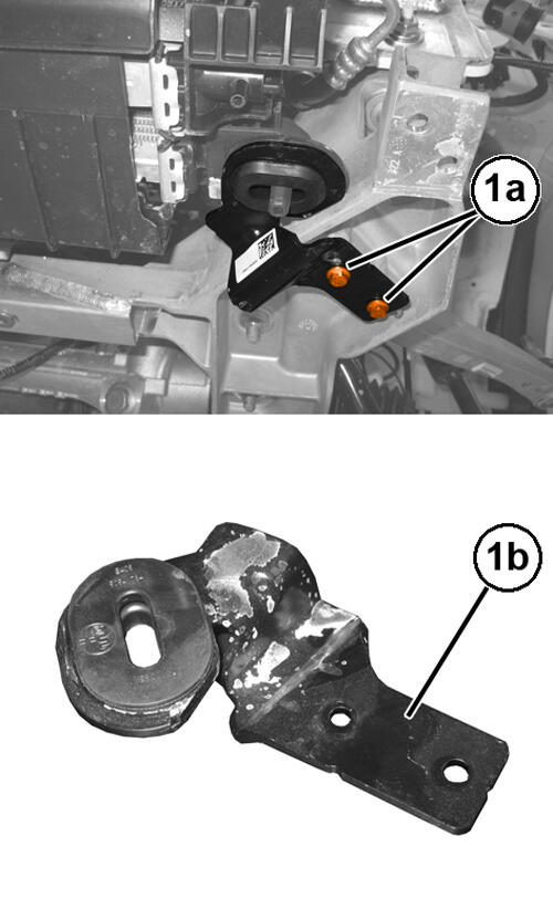
- On both sides, remove the bolts (1a) and remove the radiator mounting brackets (1b).
- Install the Power Unit Support 2000040436 (1) or (special tool #8534C, Fixture, Driveline Support).
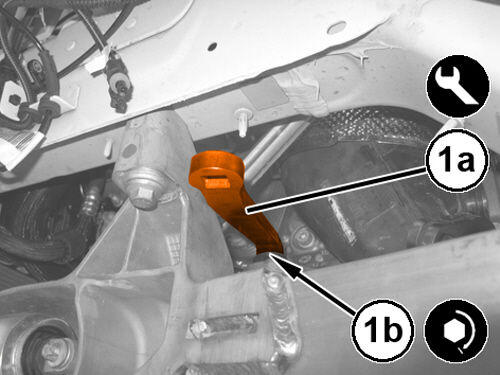
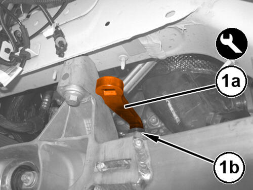
- Using the tool (1a), remove the nut (1b) attaching the engine mount bracket to the insulator on both sides.
- Place commercially available rubber spacer blocks, such as ROTFJ2427/J2440 or equivalent, on the (special tool #BX50-CHR, Table, Bishamon Lift) and position it under the crossmember assembly.
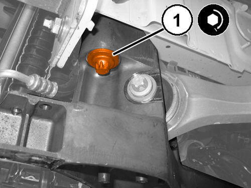
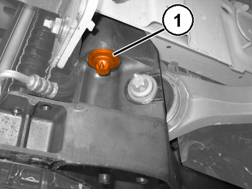
- On both sides, remove the front bolts (1) attaching the front suspension crossmember to the body.
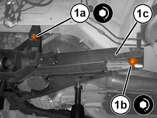
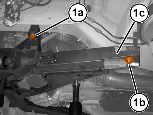
- Operating on both sides, remove the bolts (1a) and (1b) and remove the suspension crossmember (1c).
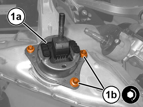
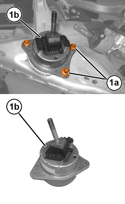
- Working on both sides, remove the attaching bolts (1a) and remove the insulators (1b) from the crossmember.
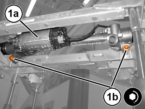
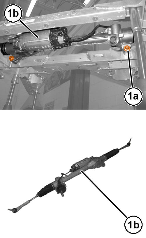
- Remove bolts (1a) and remove steering gear (1b) from the crossmember.
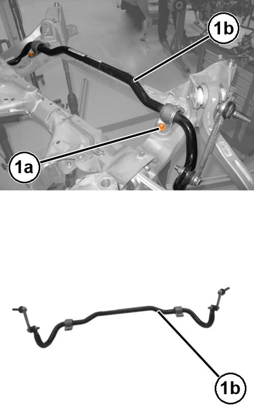
- Remove the bolts (1a) and remove the stabilizer bar (1b) from the crossmember.
INSTALLATION
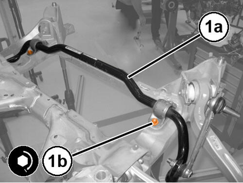
- Position the stabilizer bar (1a) in its housing and tighten the bolts (1b) to the proper specification. Refer to FRONT, TECHNICAL SPECIFICATIONS
.
- Install the steering gear (1a) and tighten the bolts (1b) to the proper specification. Refer to TECHNICAL SPECIFICATIONS
.
- On both sides, place the isolators in their seats (1a) and tighten the bolts (1b) to the proper specification. Refer to SPECIFICATIONS .
- Lift the suspension crossmember into place using the (special tool #BX50-CHR, Table, Bishamon Lift).
- On both sides, tighten to the proper the new middle bolts (1a) and rear bolts (1b) attaching the front suspension crossmember (1c) to the body. Refer to TECHNICAL SPECIFICATIONS .
- Working on both sides, tighten the front bolt attaching the front suspension crossmember to the body to the proper specification. Refer to TECHNICAL SPECIFICATIONS .
- Using the tool (1a), tighten the nut (1b) attaching the engine mount bracket to the insulator on both sides to the proper specification. Refer to SPECIFICATIONS
.
- Remove the tools used for supporting the engine.
- Place the radiator support brackets in their housings and install the respective attaching bolts.
- Connect the column (1a) to the steering gear (1b) and tighten the new bolt (1c) to the proper specification. Refer to TECHNICAL SPECIFICATIONS
.
- Connect the steering gear wire harness connectors.
- Tighten the attaching bolts and secure the automatic transmission fluid supply and return line.
- Install the new bolt attaching the shock absorber to the lower rear control arm without tightening it.NOTE:
This bolt will be tightened to torque when checking the wheel positions.
- On both sides, connect the stabilizer bar (1a) joint to the shock absorber and tighten the new nuts (1b) to the proper specification. Refer to FRONT, TECHNICAL SPECIFICATIONS
.
- Connect the wire harness connector of the oxygen sensor.
- Install the heat exchanger shield bracket in its position and tighten the relative attaching bolt.
- Tighten the new bolt attaching the A/C compressor to the proper specification. Refer to TECHNICAL SPECIFICATIONS .
- Install the front fascia. Refer to FASCIA, FRONT, REMOVAL AND INSTALLATION .
- Install the air filter housing. Refer to BODY, AIR CLEANER, REMOVAL AND INSTALLATION .
- Install the engine cover. Refer to COVER, ENGINE, REMOVAL AND INSTALLATION .
- Install the front catalytic converters. Refer to CONVERTER, CATALYTIC, REMOVAL AND INSTALLATION .
- Install the front steering knuckles. Refer to KNUCKLE, STEERING, REMOVAL AND INSTALLATION .