Removal - 2.9L
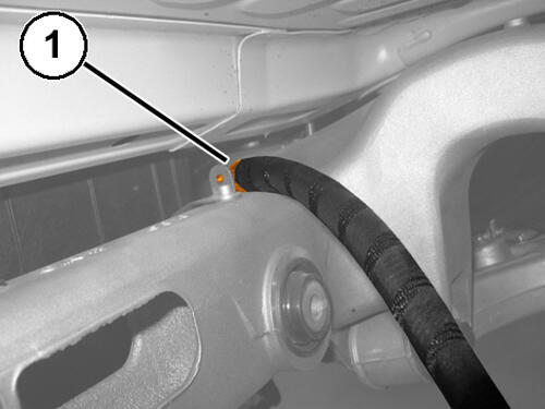
- Remove the rear differential. Refer to REMOVAL AND INSTALLATION .
- Disengage the wire harness retaining clip (1) to the bracket on the suspension crossmember.
- Place commercially available rubber spacer blocks, such as ROTFJ2427/J2440 or equivalent, on the (special tool #BX50-CHR, Table, Bishamon Lift) and position it under the crossmember assembly.
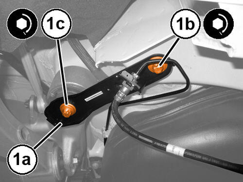
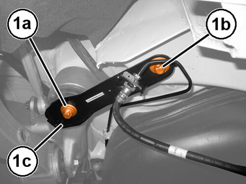
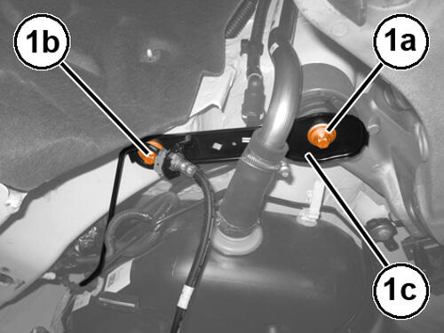
- Remove the bolts (1a), (1b) and move the right bracket complete with brake oil pipe (1c) to one side.
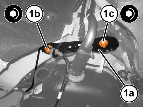
- Remove the bolts (1a), (1b) and move the left bracket complete with brake oil pipe (1c) to one side.
- Remove bolts and remove rear suspension beam.
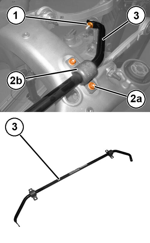
- On both sides, remove the nut (1) and disconnect the joint from the stabilizer bar.
- On both sides, loosen the bolts (2a) attaching the stabilizer bar flexible mounting (2b) to the suspension crossmember.
- Remove the stabilizer bar complete with flexible mountings.
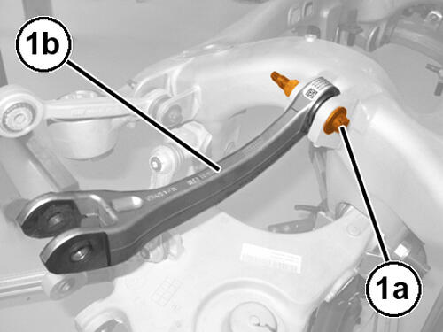
- On both sides, remove the bolt (1a) and remove the upper rear control arm (1b).
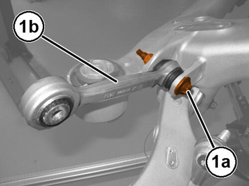
- On both sides, remove the bolt (1a) and remove the upper front control arm (1b).
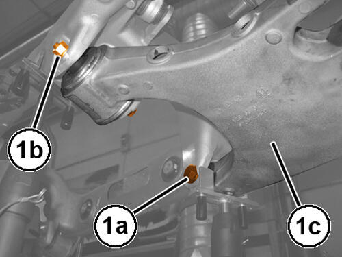
- On both sides, loosen the bolts (1a) and (1b) and remove the lower control arm (1c) complete with stabilizer bar joint.
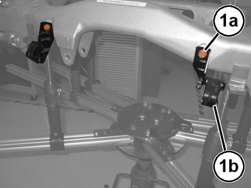
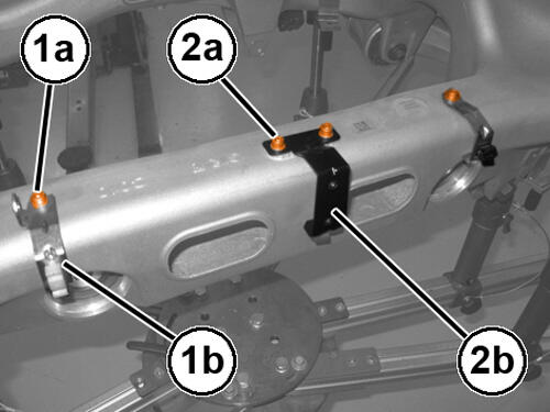
- Remove the bolts (1a) and remove the exhaust pipe support brackets (1b) complete with flexible mountings.
- Remove the bolts (1a) and remove the brackets (1b) complete with wire harness retaining clips.
- Remove the bolts (2a) and remove the exhaust silencer by-pass actuators control solenoid valve support bracket (2b).
INSTALLATION - 2.9L
- Position the exhaust silencer by-pass actuators control solenoid valve support bracket in its housing and tighten the attaching bolts to the suspension crossmember.
- Position the wire harness retaining brackets in their housings and tighten the attaching bolts to the suspension crossmember.
- Position the exhaust pipe mounting bracket complete with flexible mountings in their housings and tighten the attaching bolts to the suspension crossmember.
- Using a suitable tool, fully insert the lower control arm steel bushings in the shock absorber mounting points and in the wheel strut.
- Place the lower control arm in its housing and screw in the new bolts securing it to the suspension crossmember without tightening them.
- Place the upper front control arm in its housing and screw in the new bolt securing it to the suspension crossmember without tightening it.
- Place the upper rear control arm in its housing and screw in the new bolt to the suspension crossmember without tightening it.
- Proceed in the same way for the control arms installation.
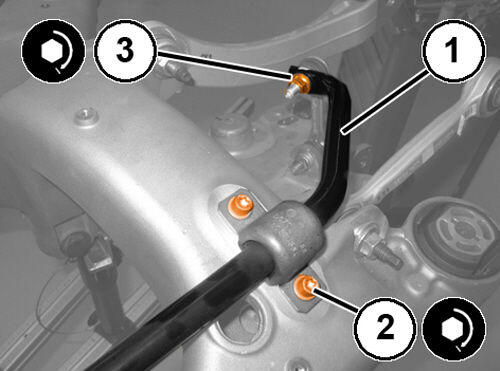
- Place the stabilizer bar (1) fitted with flexible mounting in its housing.
- On both sides, tighten the bolts (2) attaching the stabilizer bar flexible mountings to the suspension crossmember to the proper specification. Refer to TECHNICAL SPECIFICATIONS .
- On both sides, connect the joint to the stabilizer bar and tighten the new nut (3) to the prescribed torque.
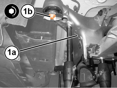
- Refit the rear suspension crossmember (1a) and tighten the new bolts (1b) to the proper specification. Refer to TECHNICAL SPECIFICATIONS
.
- Place the left bracket (1a), complete with brake oil pipe, in its housing and tighten the screw (1b) and the new screw (1c) to the proper specification. Refer to TECHNICAL SPECIFICATIONS .
- Place the right bracket (1a), complete with brake oil pipe, in its housing and tighten the screw (1b) and the new screw (1c) to the proper specification. Refer to TECHNICAL SPECIFICATIONS .
- Remove the equipment used for supporting the rear suspension crossmember.
- Install the rear differential. Refer to REMOVAL AND INSTALLATION .