Removal - 2.0L
- Remove the rear differential. Refer to REMOVAL AND INSTALLATION .
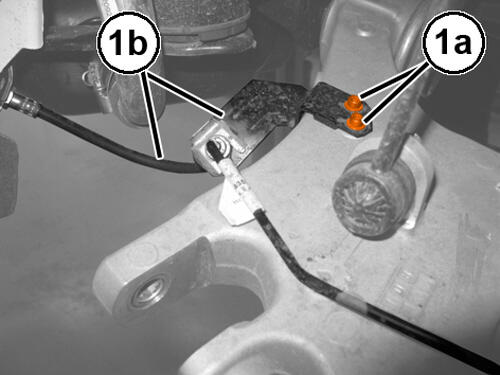
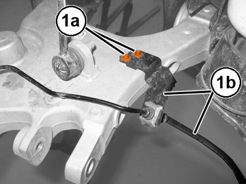
- Remove the screws (1a) and move the bracket (1b) complete with left brake lines aside.
- Remove the screws (1a) and move the bracket (1b) complete with right brake lines aside.
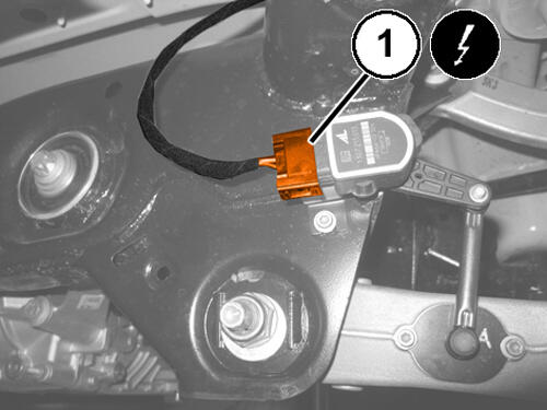
- Disconnect the wire harness connector (1) for the headlight adjustment indicator.
- Place commercially available rubber spacer blocks, such as ROTFJ2427/J2440 or equivalent, on the (special tool #BX50-CHR, Table, Bishamon Lift) and position it under the crossmember assembly.
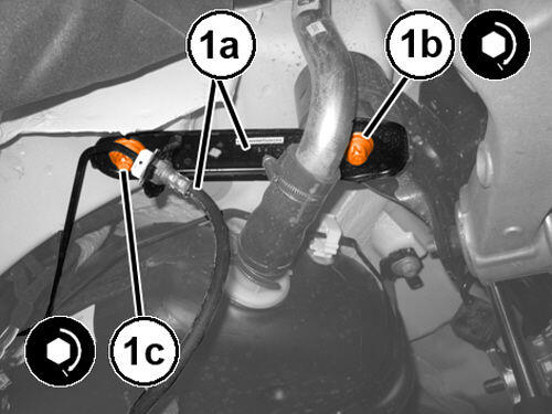
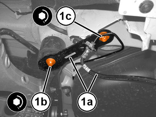
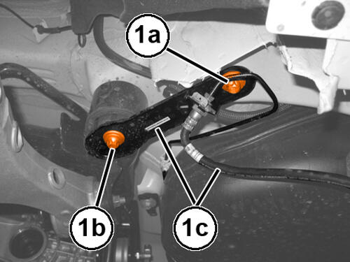
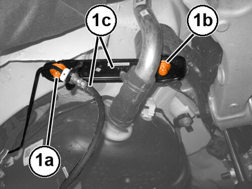
- Remove the bolts (1a), (1b) and move the right bracket complete with brake line (1c) to one side.
- Remove the bolts (1a), (1b) and move the left bracket complete with brake line (1c) to one side.
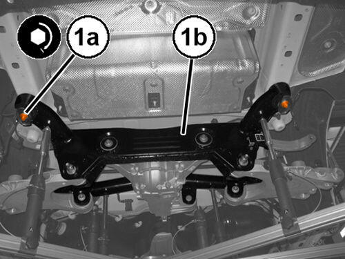
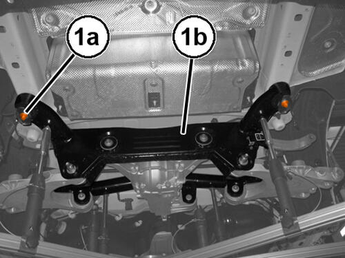
- Remove the bolts (1a) attaching the rear suspension crossmember (1b) to the body.
- Using the (special tool #BX50-CHR, Table, Bishamon Lift) lower and remove the rear suspension crossmember.
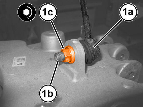
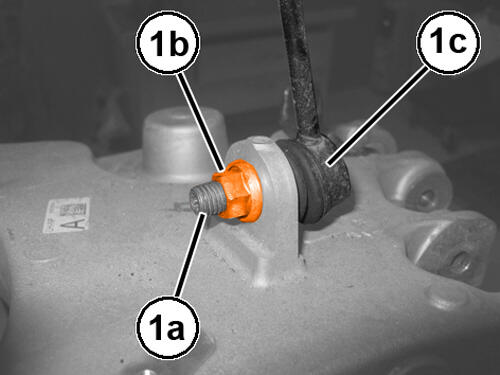
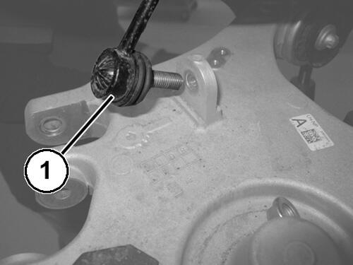
- Remove the nut (1b) fastening the stabilizer bar (1c) to the lower control arm.
- Disconnect the stabilizer bar (1) from the lower control arm.
- Proceed in the same way for the right side.
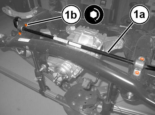
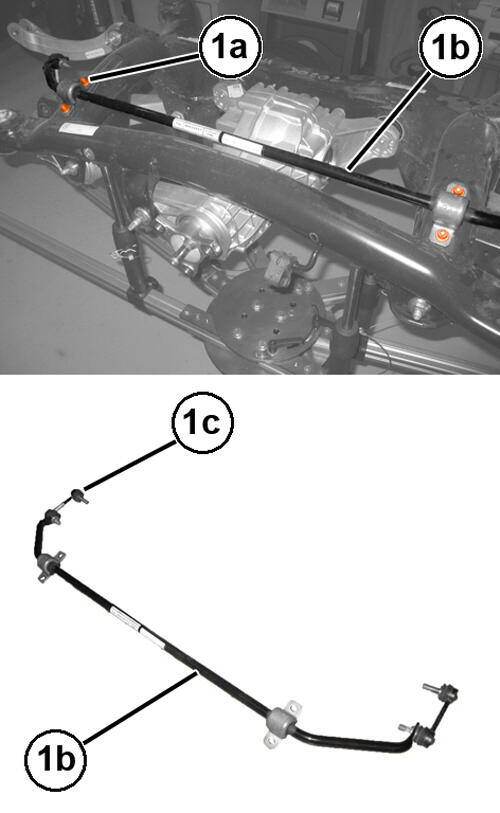
- Remove the bolts (1a) and remove the stabilizer bar (1b) complete with the links (1c).
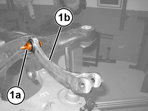
- Remove the bolt (1a) and remove the upper left suspension control arm (1b).
- Proceed in the same way for the right side.
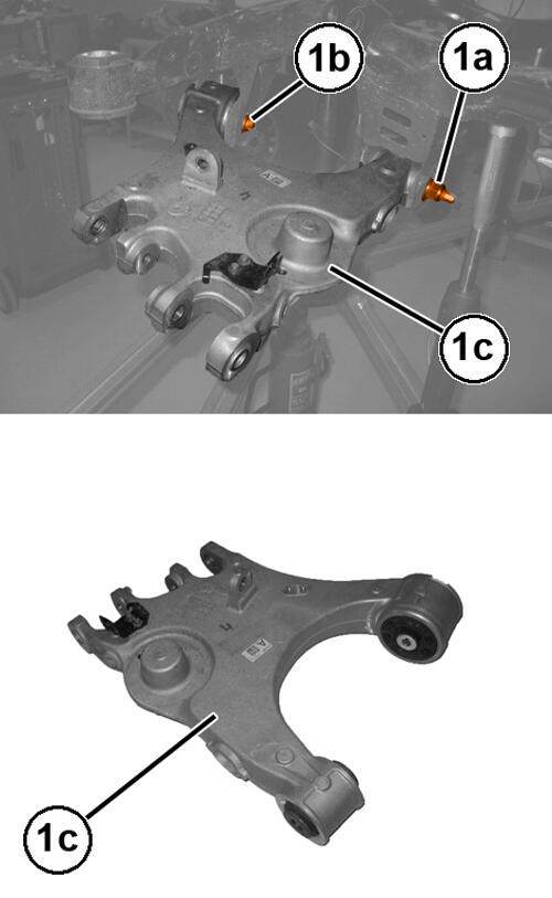
- Remove the bolts (1a), (1b) and remove the lower left control arm (1c).
INSTALLATION - 2.0L
- Using a suitable tool, fully insert the steel bushes in the lower control arm, on the wheel strut and shock absorber mount side.
- Place the lower left control arm in its housing and screw in the new bolts securing it to the rear suspension crossmember without tightening them.
- Place the front left control arm back in its housing and do up the new bolt without tightening it.
- Place the upper left control arm back in its housing and do up the new bolt without tightening it.
- Proceed in the same way for the right side.
- Place the stabilizer bar (1a) in its housing and tighten to the proper specification. Refer to TECHNICAL SPECIFICATIONS .
- Proceed in the same way for the right side.
- Connect the stabilizer bar articulation (1a) and reacting on the pin (1b), tighten the new nut (1c)to the proper specification. Refer to TECHNICAL SPECIFICATIONS .
- Place the suspension crossmember onto the (special tool #BX50-CHR, Table, Bishamon Lift).
- Tighten the new bolts (1a) securing the rear suspension crossmember (1b) to the body to the proper specification. Refer to TECHNICAL SPECIFICATIONS .
- Place the left bracket (1a), complete with brake line, in its housing and tighten the new nuts (1b) and the screw (1c) to the proper specification. Refer to TECHNICAL SPECIFICATIONS .
- Place the right bracket (1a), complete with brake line, in its housing and tighten the new nuts (1b) and the screw (1c) to the proper specification. Refer to TECHNICAL SPECIFICATIONS .
- Remove the equipment used for supporting the rear suspension crossmember.
- Connect the wire harness connector for the headlight adjustment indicator.
- Place the bracket, with rear right brake lines, in its housing and tighten the attaching screws.
- Place the bracket, with rear left brake lines, in its housing and tighten the attaching screws.
- Install the rear differential. Refer to REMOVAL AND INSTALLATION .