Left Side
WARNING: This page is about a different variant/trim than selected.
REMOVAL
- Disconnect and isolate the negative battery cable.
- Remove the back half of the left front wheelhouse splash shield. Refer to SHIELD, SPLASH, FRONT WHEELHOUSE, REMOVAL AND INSTALLATION .
- Remove the belly pan. Refer to BELLY PAN, ENGINE, REMOVAL AND INSTALLATION or BELLY PAN, REAR, REMOVAL AND INSTALLATION or BELLY PAN, REAR SUSPENSION, REMOVAL AND INSTALLATION or BELLY PAN, SIDE, REMOVAL AND INSTALLATION .
- Remove the air cleaner body. Refer to BODY, AIR CLEANER, REMOVAL AND INSTALLATION
.
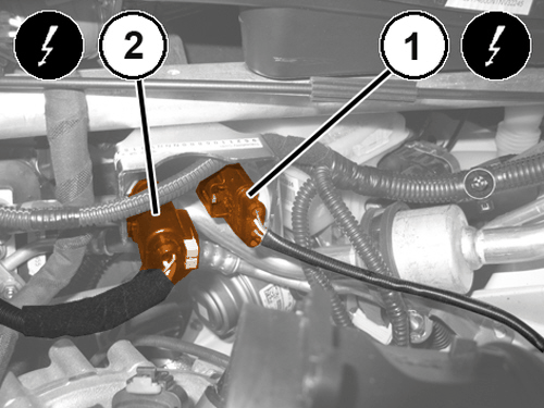
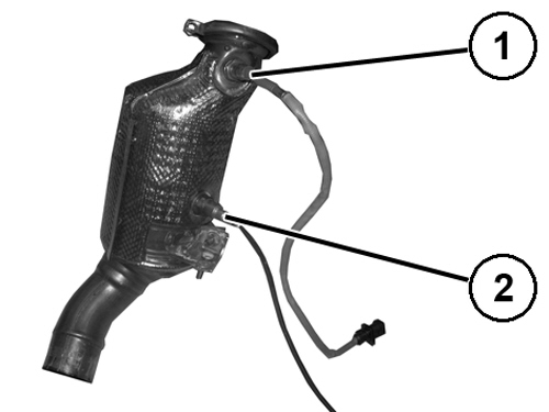
- Disconnect the rear oxygen sensor wire harness connector (1).
- Disconnect the front oxygen sensor wire harness connector (2).
- Release the clips and remove the front and rear oxygen sensor wiring.
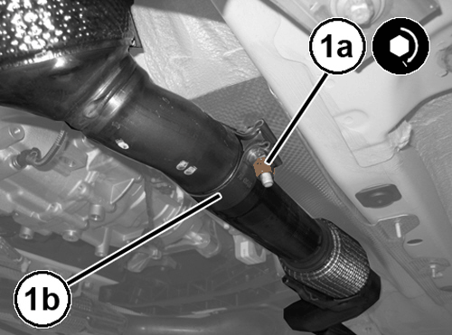
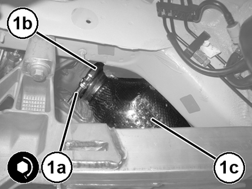
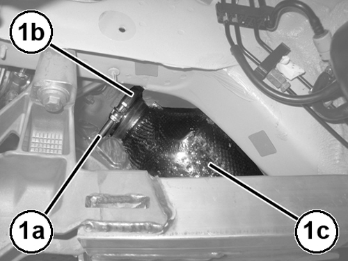
- Loosen the catalytic converter (1c) to the turbocharger collar (1b) bolt (1a).
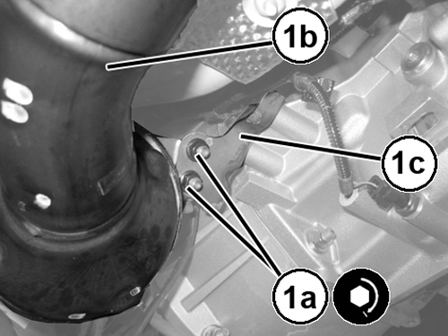
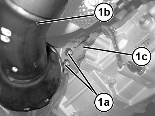
- Remove the nuts (1a) and the catalytic converter bracket (1c).
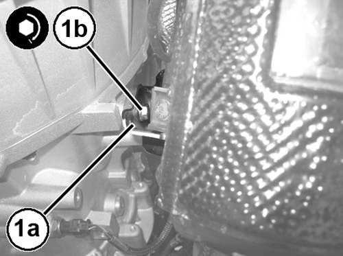
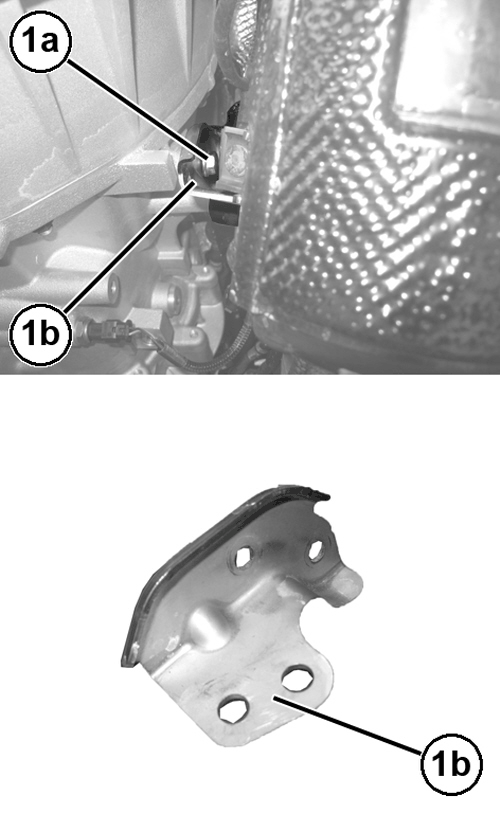
- Remove the bolts (1a) and the catalytic converter support bracket (1b).NOTE:
Adequately protect the flex joint because excessive bending could cause it to break.
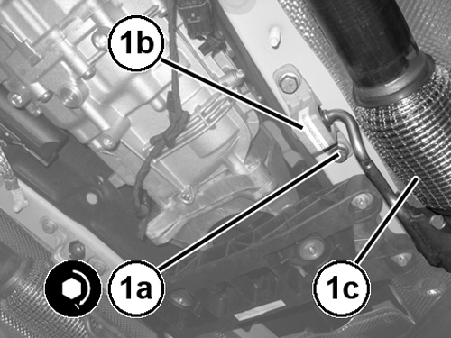
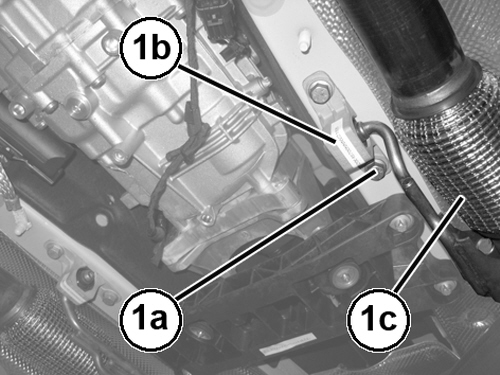
- Remove the isolator mount (1b) bolts (1a) and then remove the exhaust pipe support (1c) from isolator mount (1b).NOTE:
Adequately protect the flex joint because excessive bending could cause it to break.
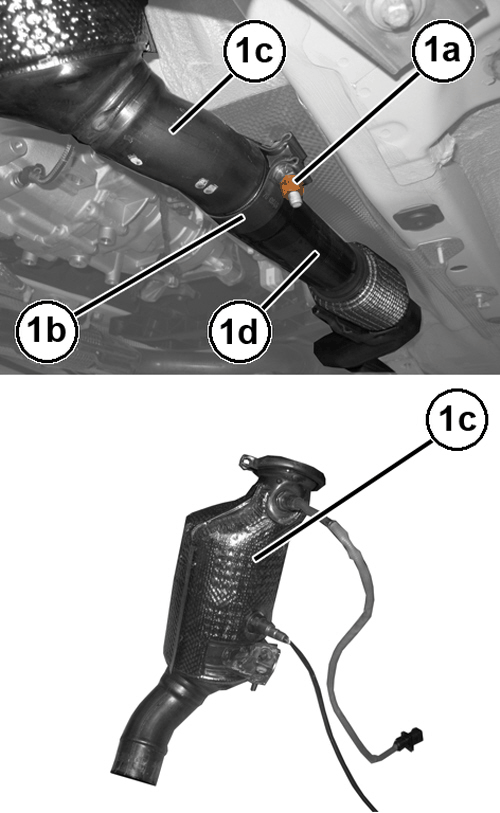
- Loosen the nut (1a), the collar (1b) and remove the left catalytic converter (1c) from the exhaust pipe (1d).
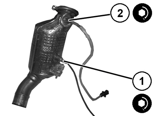
- Remove the front oxygen sensor (1) from the catalytic converter.
- Remove the rear oxygen sensor (2) from the catalytic converter.
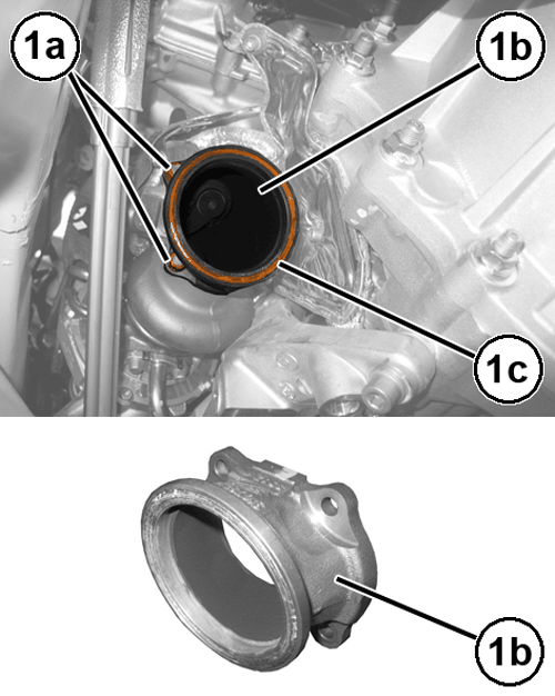
- Remove the nuts (1a) and the connector (1b) complete with seal (1c).
- Remove the gasket from the studs of the turbocharger.
INSTALLATION
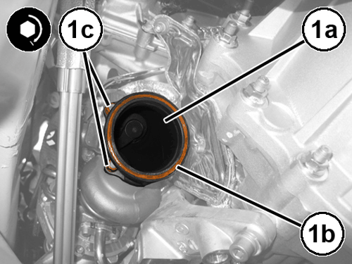
- Install a NEW gasket on the studs of the turbocharger.
- Using a NEW
seal (1b), install the connector (1a) and NEW
nuts (1c), tighten to the proper specification. Refer to TORQUE SPECIFICATIONS
.
- Install the rear oxygen sensor (1) and tighten it to the proper specification. Refer to TORQUE SPECIFICATIONS .
- Install the front oxygen sensor (2) and tighten it to the proper specification. Refer to TORQUE SPECIFICATIONS
.
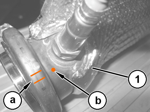
- Install the catalytic converter (1) in its housing and orient the collar by making the markings "a" with the weld spot "b" on the catalytic converter.
- Tighten the collar bolt finger tight.
- Tighten the exhaust pipe clamp nut (1a) support collar (1b) to the proper specification. Refer to TORQUE SPECIFICATIONS
.
- Install the exhaust pipe (1c) isolator mounts (1b) bolts (1a) and tighten to the proper specification. Refer to TORQUE SPECIFICATIONS
.
- Install the catalytic converter support bracket (1a) and tighten the bolts (1b) to the proper specification. Refer to TORQUE SPECIFICATIONS
.
- Tighten the catalytic converter (1b) bracket (1c) nuts (1a) to the proper specification. Refer to TORQUE SPECIFICATIONS
.
- Tighten the catalytic converter (1c) to the turbocharger collar (1b) nut (1a) to the proper specification. Refer to TORQUE SPECIFICATIONS .
- Connect the front oxygen sensor wire harness connector and engage the wiring in the retaining clips.
- Connect the rear oxygen sensor wire harness connector and engage the wiring in the retaining clips.
- Install the air cleaner body. Refer to BODY, AIR CLEANER, REMOVAL AND INSTALLATION .
- Install the belly pan. Refer to BELLY PAN, REAR, REMOVAL AND INSTALLATION or BELLY PAN, REAR SUSPENSION, REMOVAL AND INSTALLATION or BELLY PAN, SIDE, REMOVAL AND INSTALLATION .
- Install the back half of the left front wheelhouse splash shield. Refer to SHIELD, SPLASH, FRONT WHEELHOUSE, REMOVAL AND INSTALLATION .
- Connect the negative battery cable.