Disassembly And Assembly
8HP50/850RE
DISASSEMBLY
The Transmission Control Module (TCM), or Transmission Control Module Assembly (TCMA) is extremely sensitive to Electrostatic Discharge (ESD). Always use a ground strap and follow the ESD guidelines in ELECTROSTATIC DISCHARGE SENSITIVE DEVICES. Failure to follow these instructions may result in damage to the TCM/TCMA.
If the transmission is being reconditioned (clutch/seal replacement) or replaced, it is necessary to perform the TCM Adaptation Procedure. Refer to MODULE, TRANSMISSION CONTROL (TCM), MODULE PROGRAMMING .
Tag all clutch pack assemblies, as they are removed, for reassembly identification.
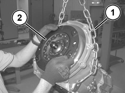
- Remove the torque converter (2).NOTE:
AWD only
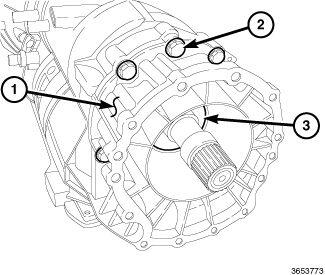
- Remove the transmission housing extension bolts (2) and remove the extension housing (1).
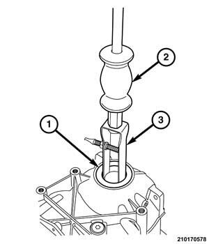
- Remove the transmission rear oil seal (3) with a suitable slide hammer and screw.NOTE:
AWD only
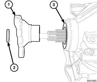
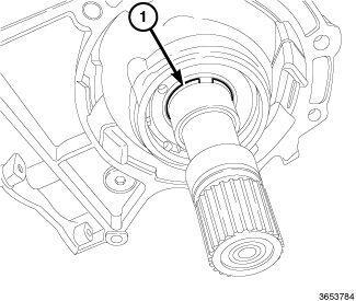
- Remove the output shaft snap ring (1) and washer.NOTE:
RWD only.
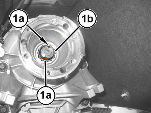
- Remove the output shaft flange locknut (1b) staking (1a).NOTE:
RWD only.
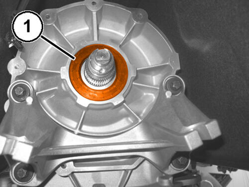
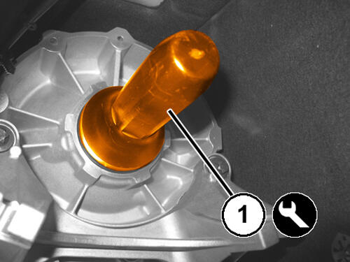
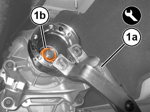
- Using a flange holder (special tool #C-3281, Holder, Flange) (1a), remove the output shaft flange nut (1b).NOTE:
RWD shown in illustration, AWD similar.
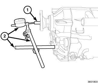
NOTE:End play specification is between 0.11 - 0.42 mm (0.0043 - 0.0165 in.). If end play is outside this range, a different selectable end play shim must be used during assembly.
- Measure the output shaft (1) end play as follows:
- Attach a dial indicator (2) and position the plunger against the end of the output shaft (1).
- Zero the dial indicator (2).
- Move the output shaft (1) in and out, and record the maximum travel for assembly reference.
NOTE:RWD only.
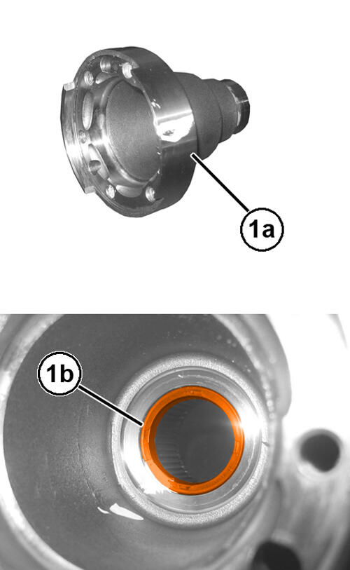
- Remove the output shaft flange (1a) and inspect the output shaft flange sealing surface (1b) for damage, replace as needed.
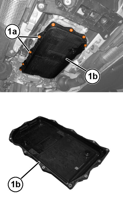
- Remove the thirteen oil pan retaining bolts (1a).NOTE:
Inspect the gasket for reuse. If the seal is cut or torn, replace the gasket.
- Carefully remove the oil pan and gasket (1b).
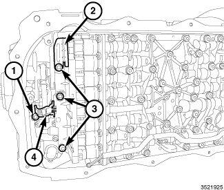
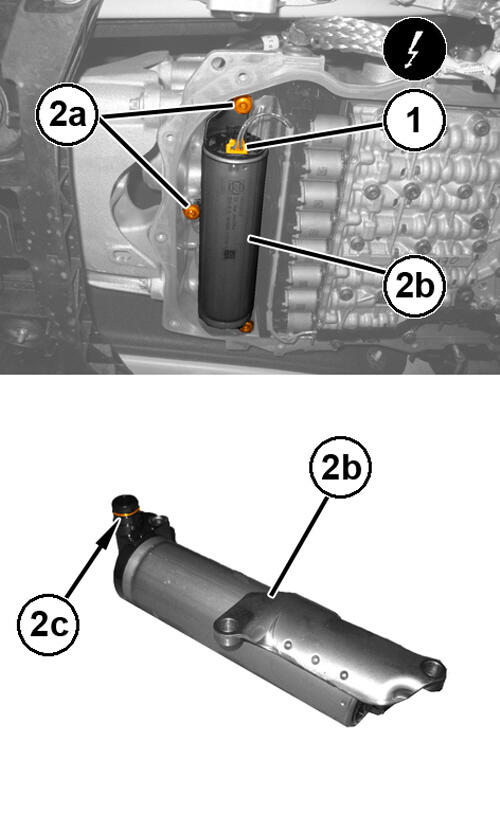
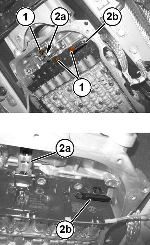
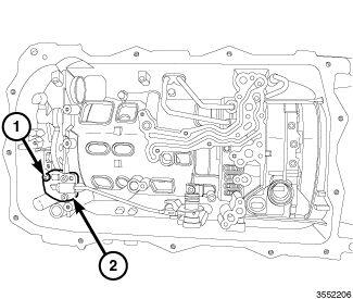
- If equipped, disconnect the Hydraulic Impulse Oil Storage (H.I.S) connector (1).
- If equipped, remove three bolts (2a) and the H.I.S. accumulator (2b).
- Remove the valve body assembly end retainer bolts (1).
- Lift the electrical connector lock (2b) to release the internal harness end from inside the transmission for valve body assembly removal.
- Remove the Output Speed Sensor (OSS) bolt (1) and pull the OSS (2a) loose from the case.
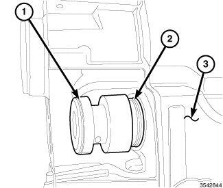
- Using (special tool #10377, Remover/Installer, Guide Sleeve) (1) carefully pull the electrical harness insulator (2) straight out from the transmission case (3).
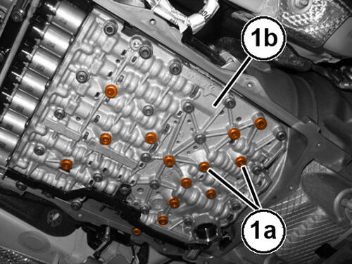
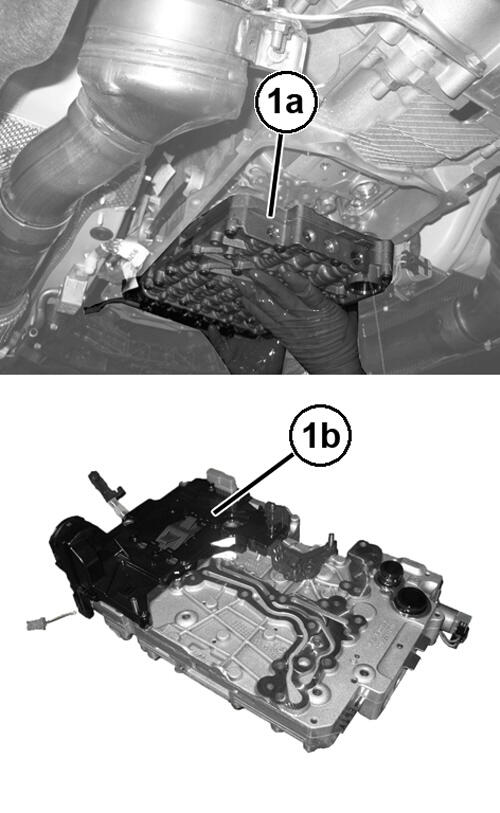
- Remove the valve body assembly (1b) bolts (1a).
- Carefully remove the valve body assembly (1a) from the transmission.NOTE:
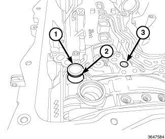
The fluid port (1) may be in the transmission or the valve body assembly.
- Pull the fluid port (1) from the transmission or valve body assembly.
- Remove the two O-rings (2).
- Remove the compression seal (3) from the transmission.
- Remove and discard the fourteen oil pump housing retaining bolts (1).NOTE:
Remove the input shaft o-ring before the oil pump is removed.
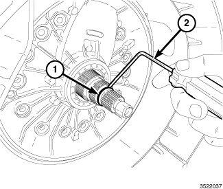
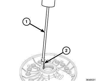
- Remove the input shaft O-ring (1) using a small pick (2) or equivalent.
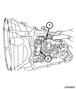
- Carefully pry the oil pump housing (1) away from the case (2) with a small flat blade screwdriver or equivalent through the case opening.
- From the front of the transmission, remove the oil pump housing.NOTE:
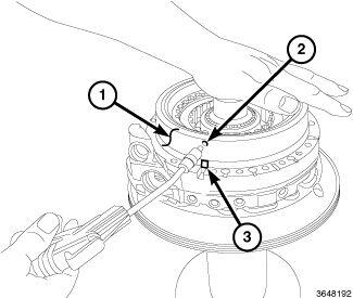
Apply air pressure slowly because oil may spray when B-piston releases from the assembly.
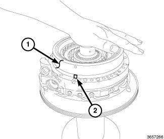
- With one hand above B-piston (1), carefully apply air pressure into the hole (2) directly above the B-piston alignment tab (3) to remove B-piston (1) from the assembly.
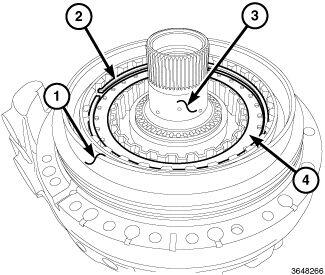
- Remove the outer ring (1) (under B-piston).
- Remove the snap ring (2).
- Remove the clutches and spacers (4).
- Remove the hub (3).
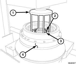
- Position the oil pump housing assembly (4) in a suitable arbor press.
- Using (special tool #8285, Compressor, Spring) (1), press on the fingers of the piston retaining ring to remove tension, and remove the two halves of the split retainer ring (2, 3).
- Remove the piston retaining ring and piston below it.
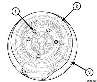
- Remove the six bolts (1) and separate the oil pump housing (2) from the oil pump cover (3).
- Using (special tool #9667, Remover, Seal) (2) and (special tool #C-3752, Slide Hammers) (1), remove the oil seal from the front pump cover.
- Remove the outer lip seal from the front pump cover.
- Remove the snap ring.
- Using (special tool #6787A, Remover, Bearing Cup) (1) and (special tool #C-3752, Slide Hammers) (2) remove the needle bearing from the front cover (3).
- Remove the snap ring.
- Using (special tool #9585, Remover, Bearing Cup) and (special tool #C-637, Slide Hammer, Universal) remove the needle bearing.
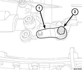
- Remove the manual park release lever retaining nut (2) and remove the lever (1).
- Remove the three park pawl lock rod guide plate retaining screws (1) and remove the plate (2).
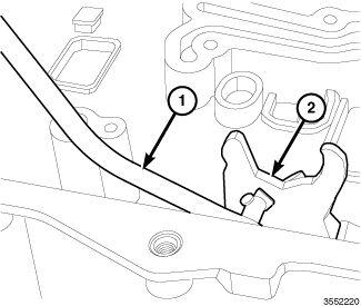
- Remove the park pawl lock rod (1) from the fork (2).NOTE:
Pay attention to the spring position for installation.
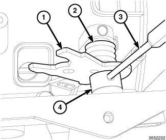
- Remove the roll pin from the selector shaft (4) using a suitable pin punch (3).
- Remove the shaft (4), spring (2) and fork (1) from the case.
- Remove the selector shaft seal using a small screwdriver or equivalent.
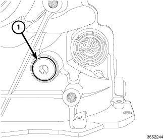
- Remove the park pawl shaft plug (1) from the rear of the case.NOTE:
Pay attention to the spring position for installation.
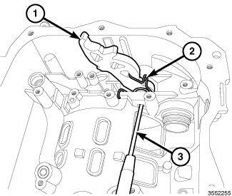
- Remove the park pawl shaft using a suitable pin punch (3), remove the park pawl (1) and spring (2).NOTE:
The transmission must be in a vertical position before the main stack is removed, so damage to the drums does not occur.
- Remove the input/output shaft and P4 annulus drum assembly (1) from the case.
- Using
(special tool #8912, Remover, Bearing)
and
(special tool #C-637, Slide Hammer, Universal)
remove the output seal.
NOTE:AWD shown in illustration, RWD similar. The AWD bearing is a needle bearing and the RWD is a ball bearing.
- Remove the outer bearing snap ring (1), and the outer needle bearing (2) (AWD) or outer ball bearing (RWD).NOTE:
AWD shown in illustration, RWD similar.
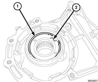
- Remove the oil dam snap ring.
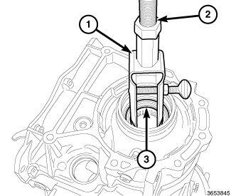
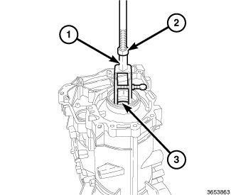
- Using (special tool #9664, Remover, Bearing Cup) (1) and (special tool #C-637, Slide Hammer, Universal) (2), remove the oil dam (3).NOTE:
AWD shown in illustration, RWD similar.
- Remove the output shaft inner needle bearing (AWD) or inner ball bearing (RWD) snap ring.
- Using (special tool #9664, Remover, Bearing Cup) (1) and (special tool #C-637, Slide Hammer, Universal) (2), remove the inner ball bearing (3).
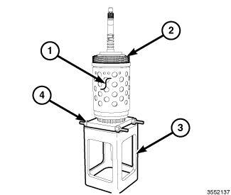
- Position the input/output shaft and P4 annulus drum assembly (1) on (special tool #8925-3, Assembly, Press Fixture) (3) and (special tool #1130, Splitter, Bearing/Gear) (4).
- Remove the B clutch pack (2).
- Remove the O-ring and 5 squared O-rings.
- Remove the P1 annulus/B clutch hub assembly (1) from the P4 annulus drum.NOTE:
The washer may stick to the bottom of the P1 annulus/B clutch hub assembly (1).
- Remove the selectable shim from the P1 annulus/B clutch hub.
- Remove the needle bearing and holding plate (2) from the P1 planetary carrier.NOTE:
The (special tool #10378, Rings, Support) are three pieces intended to be used in multiple locations around the drum.
- Position the (special tool #10378, Rings, Support) (1) on the P4 annulus drum assembly to protect the drum.NOTE:
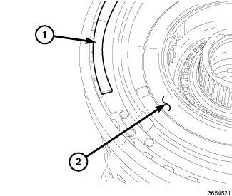
Pry the snap ring from the opposite side of the snap ring openings to release.
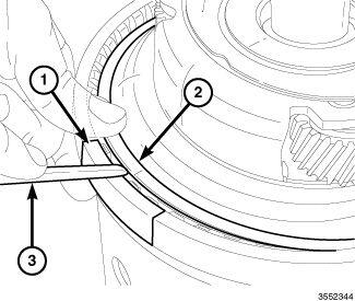
NOTE:When the snap ring is removed the internal clutch drum may drop slightly.
- Using a suitable tool (3), release the snap ring (2) by prying in and up from the opposite side of the snap ring openings.
- Remove the P1 planetary carrier (3).
- Remove P1/P2 sun gear from the bottom of the P1 planetary carrier (3).NOTE:
Be careful not to damage the P2 carrier magnetic pick up for the input sensor.
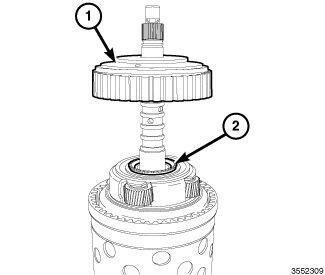
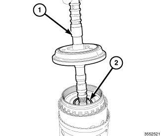
- Remove the input shaft with P2 planetary carrier (1) from the drum assembly.
- Remove the needle bearing (2) and washer.
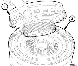
- Remove the P2 annulus/P3 sun gear (1) from the drum assembly (2).
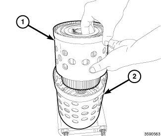
- Remove the D clutch drum (1) from the P4 annulus drum (2).NOTE:
The (special tool #10378, Rings, Support) are three pieces intended to be used in multiple locations around the drum.
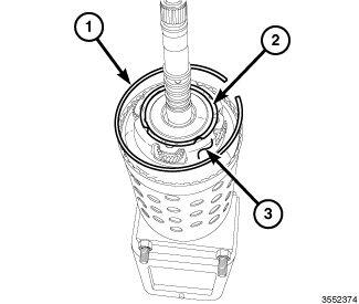
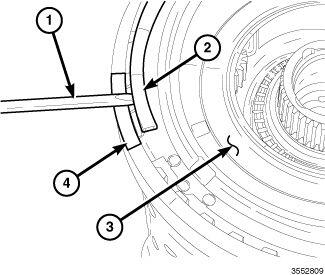
- Position the (special tool #10378, Rings, Support) (4) on the P4 annulus drum assembly to protect the drum.
- Using a suitable tool (1), release and remove the snap ring (2).
- Remove the P3 planetary carrier (3).
- Remove the needle bearing from the planetary carrier.
- Remove the P4 sun gear/C/E clutch retainer (1) from the D clutch drum (2).
- Remove the snap ring (1) from the P4 sun gear/C/E clutch retainer (2).
- Remove the P3 annulus (1) from the P4 sun gear/C/E clutch retainer (2).
- Remove the snap ring (1) from the P4 sun gear/C/E clutch retainer (2).
- Remove the E clutch (1) from the P4 sun gear/C/E clutch retainer (3).
- Remove the needle bearing (2) from the E clutch (1).NOTE:
The E clutch and C clutch are similar. The C clutch hub is removable and has 6 fricton plates.
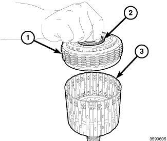
- Remove the C clutch (1) from the P4 sun gear/C/E clutch retainer (2).
- Remove the bearing from top and bottom of C clutch (1).
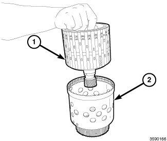
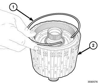
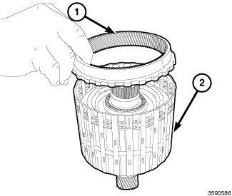
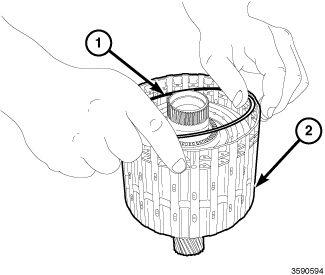
- Remove the P4 planetary carrier/output shaft (2) from the P4 annulus drum (1).
- Remove the snap ring (1) from the P4 annulus drum (2).
- Remove the P4 annulus (3) from the P4 annulus drum (2).
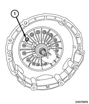
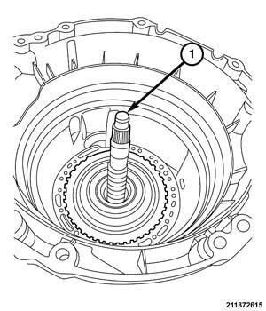
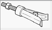
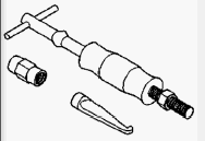
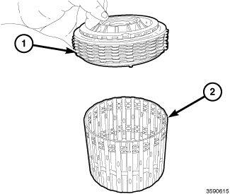
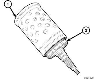
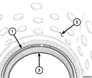
A unique transmission fluid has been developed for this transmission. This fluid is NOT compatible with ATF+4 or any other current FCA US LLC transmission fluid. For specifics about this unique fluid see FLUIDS, LUBRICANTS AND GENUINE PARTS.
The Transmission Control Module (TCM), or Transmission Control Module Assembly (TCMA) is extremely sensitive to Electrostatic Discharge (ESD). Always use a ground strap and follow the ESD guidelines in ELECTROSTATIC DISCHARGE SENSITIVE DEVICES. Failure to follow these instructions may result in damage to the TCM/TCMA.
If the transmission is being reconditioned (clutch/seal replacement) or replaced, it is necessary to perform the TCM Adaptation Procedure. Refer to MODULE, TRANSMISSION CONTROL (TCM), MODULE PROGRAMMING .
ASSEMBLY
- Insert the P4 annulus (3) into the P4 annulus drum (2).
- Install the snap ring (1) into the P4 annulus drum (2).
- Install the P4 planetary carrier\output shaft (2) into the P4 annulus drum (1).
- Position the bearings on the top and the bottom of C clutch (1).
- Install the C clutch (1) into the P4 sun gear/C/E clutch retainer (2).
- Install the needle bearing (2) onto the E clutch (1).
- Install the E clutch (1) into the P4 sun gear/C/E clutch retainer (3).
- Install the snap ring (1) into the P4 sun gear/C/E clutch retainer (2).
- Install the P3 annulus (1) into the P4 sun gear/C/E clutch retainer (2).
- Install the snap ring (1) into the P4 sun gear/C/E clutch retainer (2).
- Install the P4 sun gear/C/E clutch retainer (1) into the D clutch drum (2).
- Install the needle bearing onto the planetary carrier.
- Install the P3 planetary carrier (2) in the D clutch drum.
- Install the snap ring (1).
- Install the D clutch drum (1) into the P4 annulus drum (2).
- Install the P2 annulus\P3 sun gear (1) onto the drum assembly (2).
- Install the needle bearing (2) and washer.
- Install the input shaft with P2 planetary carrier (1) into the drum assembly.
- Install P1/P2 sun gear into the bottom of the P1 planetary carrier (3).
- Install the P1 planetary carrier (3).
- Install the snap ring (1).
- Install the needle bearing and holding plate (2) onto the P1 planetary carrier.
- Install the selectable shim to the P1 annulus/B clutch hub.
- Install the P1 annulus\B clutch hub assembly (1) onto the P4 annulus drum.
- Install the O-ring and five squared O-rings.
- Install the clutch pack (2).NOTE:
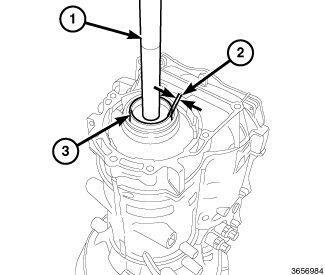
The (special tool #10373, Installer, Output Needle Bearing/Rear Oil Dam) (3) is a combination tool that is reversed to install the oil dam and output shaft inner needle bearing. For use to install the output shaft inner needle bearing, use the thick walled side (2) of the tool against the bearing.
- Using (special tool #10373, Installer, Output Needle Bearing/Rear Oil Dam) (3) and (special tool #C-4171, Driver Handle, Universal) (1), install the output shaft inner needle bearing.
- Install the snap ring.NOTE:
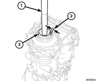
The (special tool #10373, Installer, Output Needle Bearing/Rear Oil Dam) (3) is a combination tool that is reversed to install the oil dam and output shaft inner needle bearing. For use to install the oil dam, use the thin walled side (2) of the tool against the oil dam.
- Using (special tool #10373, Installer, Output Needle Bearing/Rear Oil Dam) (3) and (special tool #C-4171, Driver Handle, Universal) (1), install the oil dam.
- Install the snap ring.
- Install the needle bearing (AWD) or ball bearing (RWD).
- Install the snap ring (1).NOTE:
The transmission must be in a vertical position when installing the main stack, so damage to the drums does not occur.
- Install the input/output shaft and P4 annulus drum assembly (1) into the case.
- From outside the transmission case, install the park pawl shaft and install the park pawl (1) and spring (2).
- Install the park pawl shaft plug (1) into the rear of the case and tighten to the proper. Refer to TORQUE SPECIFICATIONS
.
- Using (special tool #6936, Spacer) (1), install the selector shaft seal (2).
- Install the shaft (4), spring (2), and fork (1) into the case.
- Install the roll pin into the selector shaft (4) using a suitable pin punch (3).
- Install the park pawl lock rod (1) onto the fork (2).
- Position the park pawl lock rod guide plate (2), install the three park pawl lock rod guide plate retaining screws (1) and tighten to the proper. Refer to TORQUE SPECIFICATIONS
.
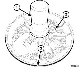
- Install the oil pump cover lip seal (3) on the oil pump cover (2).
- Using (special tool #10375, Installer, Oil Pump Cover Oil Seal) (1), install the input shaft seal in the oil pump cover (2).
- Position the oil pump housing (2) and oil pump cover (3) together.
- Install the five bolts (1) and tighten to the proper. Refer to TORQUE SPECIFICATIONS .
- Insert the piston and the retaining ring (1) into the housing.
- Position the oil pump housing assembly (4) in a suitable arbor press.
- Using (special tool #8285, Compressor, Spring) (1), press on the fingers of the piston retaining ring to remove tension, and install the two halves of the split retainer ring (2).
- Install the hub (3).
- Install the clutches and spacers (4).
- Install the snap ring (2).
- Install the outer ring (1) (below B-piston).
- Position the B-piston alignment tab (2) above the notch and install B-piston (1) on the assembly.
- Carefully position the oil pump housing assembly into the case.
- Install the new
input shaft O-ring.NOTE:
Firmly press the oil pump in place before drawing it in with bolts.
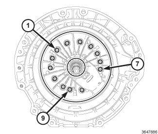
- Install the thirteen oil pump cover retaining bolts and tighten the oil pump cover as follows:
- In order to seat the oil pump cover properly, pre tighten bolts one, seven and nine to 6 N.m (53 in. lb.).
- Working in a clockwise pattern, beginning with number one, tighten to 10 N.m (89 in. lb.).
- Working in a clockwise pattern, beginning with number one, tighten an additional 90°.
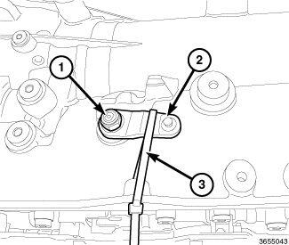
NOTE:The manual park release lever (2) can be reversed to release tension and ease the installation of the valve body assembly.
- Temporarily install the manual park release lever (2) to release tension on the shift fork as follows:
- Install the manual shift shaft lever (2) 180 degrees offset from its original position.
- Install the nut (1) and hand tighten.
- Turn the manual park release lever (2) and using a tie strap (3), secure the lever (2) into position so the park release fork is in the same position as it was before valve body assembly removal.
- Install a new compression seal (3) into the transmission case.
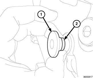
- Install the fluid port (1) with new
O-rings to the transmission case.
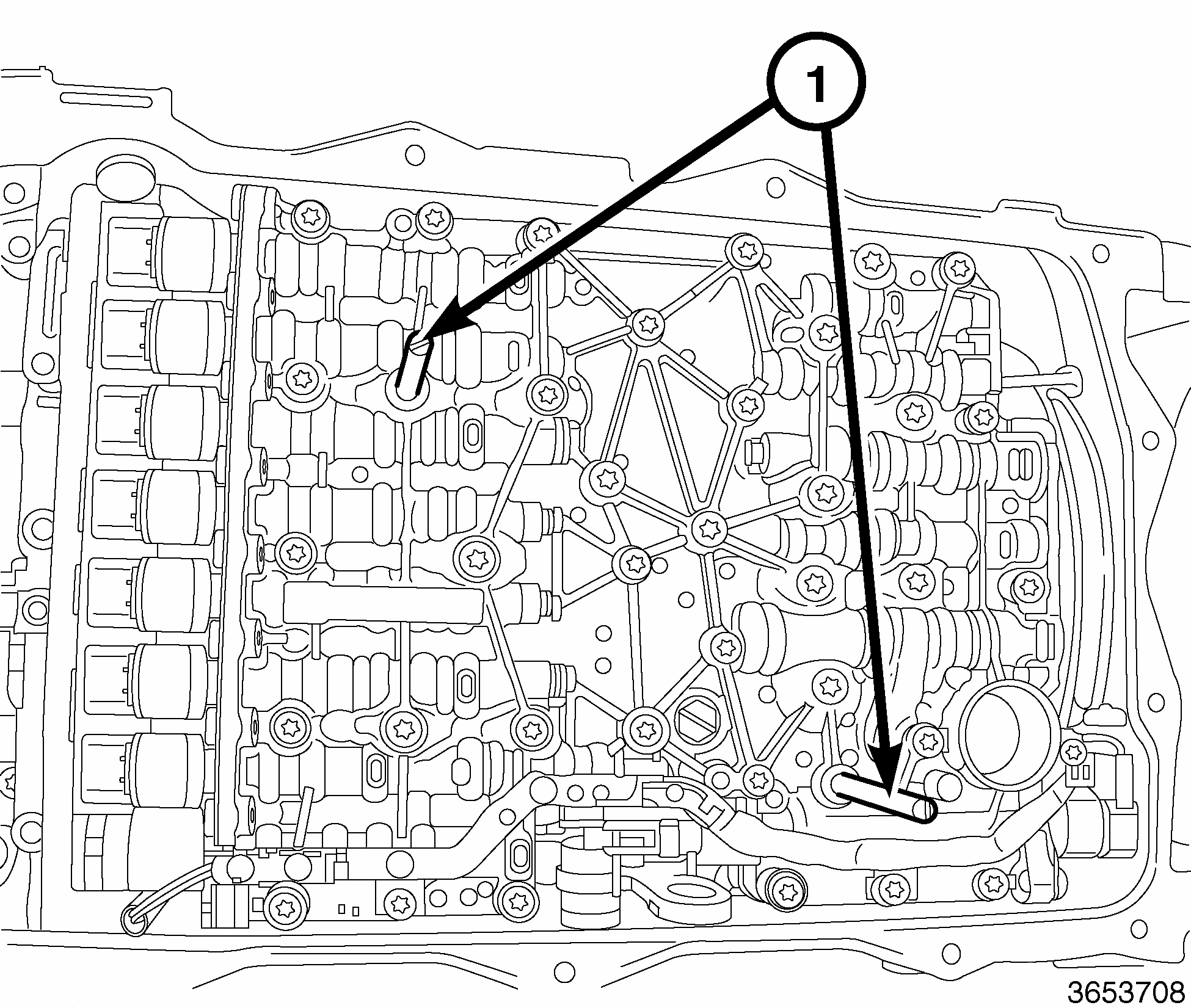
- Install the (special tool #10379, Pins, Valve Body Alignment) (1) in the transmission case as guides for the valve body assembly.NOTE:
Make sure the shift fork lines up properly.
- Using the valve body alignment pins (1) to guide, position the valve body assembly to the transmission.NOTE:
After several bolts have been hand tightened, remove the guide pins (1).
- Install the fourteen valve body assembly retaining bolts and hand tighten.
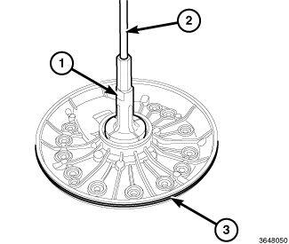
- Using (special tool #10377, Remover/Installer, Guide Sleeve) (1) carefully install the electrical harness insulator (2) into the transmission case (3).
- Install the sensor (4) and the sensor retaining bolt (1) and hand tighten.
- Latch the electrical connector insulator lock (2) by pushing in.
- Install the OSS (1a) in the case install the OSS bolt (1b) and tighten to the proper. Refer to TORQUE SPECIFICATIONS
.
- If equipped, install the Hydraulic Impulse Oil Storage (H.I.S.) accumulator (2b).
- Tighten the bolts (2a) to the proper. Refer to TORQUE SPECIFICATIONS .
- Connect the H.I.S. electrical connector (1).
- Install the valve body assembly end retainer bolts and hand tighten.
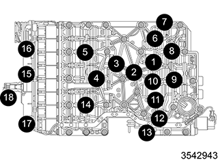
- Tighten the valve body assembly retaining bolts 1-18 in the sequence shown in illustration to 8 N.m (71 in. lbs.).
- Remove the tie strap and return the manual release lever (1) to the original position.
- Install the nut (2) and tighten to the proper. Refer to TORQUE SPECIFICATIONS .
- Position the oil pan and gasket.
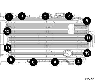
- Install the thirteen oil pan retaining bolts and using the sequence shown in illustration and tighten to 10 N.m (89 in. lbs.).NOTE:
AWD only.
CAUTION:The seal must be installed flush with the case. Driving the seal deeper could damage the seal causing a leak.
- Position the new output shaft seal (1) over the output shaft and against the transmission case.
- Using (special tool #9677, Installer, Seal) (1) install the output shaft seal.
- Position the extension housing.
- Install the seven transmission housing extension bolts (2) and tighten to the proper. Refer to TORQUE SPECIFICATIONS
.NOTE:
RWD only.
- Install the transmission output shaft washer.CAUTION:
The seal must be installed flush with the case. Driving the seal deeper could damage the seal causing a leak.
- Position the new output shaft seal (1) over the output shaft and against the transmission case.
- Using (special tool #9677, Installer, Seal) (1) install the output shaft seal.
- Install the output shaft flange (1a).
- Install the new output shaft flange nut and washer (1b) using a 34 mm 12 point socket and (special tool #C-3281, Holder, Flange) (1a) to hold the flange (1). Tighten to the proper. Refer to TORQUE SPECIFICATIONS .
- Stake the nut (1b).
- Install the torque converter (2).
- Before installing the transmission in the vehicle, pre-fill the transmission as outlined in FILL TRANSMISSION AFTER SERVICE. Refer to TRANSMISSION FILL AFTER SERVICE .