Description And Operation
DESCRIPTION
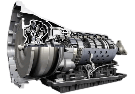
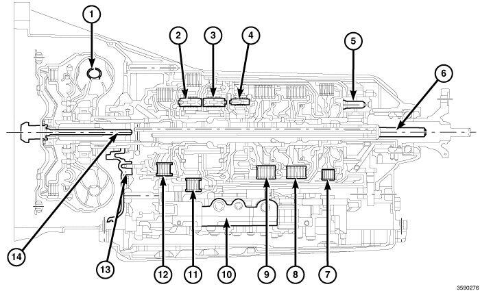
A unique transmission fluid has been developed for this transmission. This fluid is NOT compatible with ATF+4 or any other current FCA US LLC transmission fluid. For specifics about this unique fluid see FLUIDS, LUBRICANTS AND GENUINE PARTS.
The transmission case is a single-piece unit. The starter pocket, cooler line fittings, and manual park release lever are located on the driver's side of the case. The transmission wire harness connector and oil fill plug are located on the passenger side of the case. The two-wheel drive model uses a flanged output shaft connection. The four-wheel drive model uses a sealed, externally-splined output shaft to form a dry connection between the adapter plate and the transfer case.
Identification
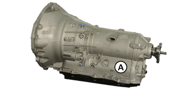
In the area of location (A) there are two barcodes and their corresponding alphanumeric codes. The top code identifies the COMPONENT TRACKING NUMBER. The bottom code identifies the PART NUMBER.
OPERATION
- The 8HP75 is an electronic eight-speed automatic transmission.
- The Transmission Control Module Assembly (TCMA), which is integrated into the valve body, provides fully synchronized clutch-to-clutch shifting through four planetary gear sets.
- The TCMA includes a mounting plate that holds the Transmission Control Module (TCM) and a molded wiring harness for connection to various transmission sensors and solenoids.
- The valve body assembly contains all the sensors and solenoids required for operation, completely inside the transmission.
- Eight speeds allow the engine to maintain its optimal RPM range, increasing fuel economy and performance.
- Transmission control is performed by the TCM based on hard-wired and CAN bus signals from sensors and modules.
- The TCM receives driveability data from the Powertrain Control Module (PCM) and other modules over the CAN-C bus.
- It also receives shift lever position information from the electronic shifter over a dedicated transmission CAN bus.
- The TCM processes this input data and controls operation of the torque converter clutch, park lock system, solenoid valves, and pressure regulating valve.
- The input and output speed sensors are Hall-effect sensors that measure shaft rotational speed.
- The input speed sensor is located at the top, near the center, of the of the TCMA and reads input shaft speed from the magnetic ring on the P2 carrier.
- The output speed sensor is located at the back of the TCMA and reads output shaft speed from the P4 carrier.
| GEAR | RATIO |
| 1st | 5.000 |
| 2nd | 3.200 |
| 3rd | 2.143 |
| 4th | 1.720 |
| 5th | 1.313 |
| 6th | 1.00 |
| 7th | 0.823 |
| 8th | 0.640 |
| Reverse | 3.478 |
FILTER SERVICE
- The 8HP75 has a conventional fluid sump design, however, the transmission oil filter is integrated into the transmission oil pan resulting in a lower profile for improved vehicle packaging.
- The transmission oil pan gasket is reusable providing it is not damaged during removal.
- If the gasket is damaged inspect the transmission oil pan for damage.
- Replace the transmission oil pan gasket or the transmission oil pan and gasket as an assembly.
FLUID CHECK AND FILL
- A transmission fluid fill tube and indicator are not provided.
- All work is performed under the vehicle while raised on a hoist. In the event of a transmission shift quality concern, a fluid leak, or in conjunction with a transmission repair, the transmission fluid level must be validated and topped off as necessary.
- The procedure involves the use of a scan tool to monitor transmission fluid temperature.
- Specific service procedures are necessary to check and fill the transmission with fluid. Refer to CHECK FLUID LEVEL .
Epicyclic Gear Sets
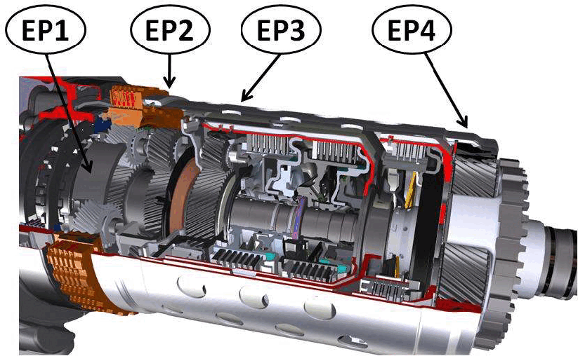
EP (1, 2, 3, 4) epicyclic gear train
The 8 forward gears and reverse are implemented by connecting four single-arm epicyclic gear trains.
The two front gear trains have a common sun gear, while the power is always output through the fourth epicyclic gear train planet carrier.
Engagement Elements
There are five engagement elements divided as follows:
| Brakes | A | B | |
| Clutches | C | D | E |
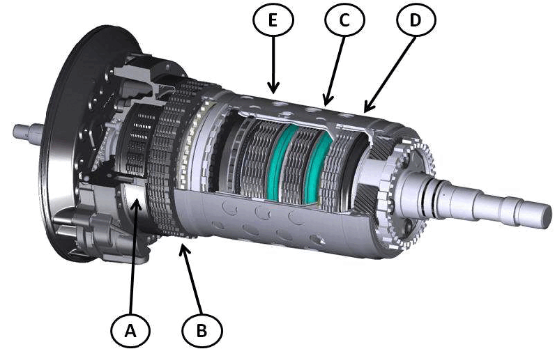
Multiple-disc clutches C, D and E transmit the engine torque to the epicyclic gear train, while brakes A and B offload the engine torque to the transmission housing.
The engagement elements are hydraulically closed. The fluid pressure compresses the disc pack to engage the clutch. When the hydraulic pressure decreases, the diaphragm spring pushes the piston into its rest position.
The engagement elements serve to engage the gears under load without interrupting the traction force.
For each gear, three engagement elements are always closed, therefore two engagement elements always remain open. Each open engagement element creates drag torque, so this configuration allows an increase in transmission efficiency.
Brakes
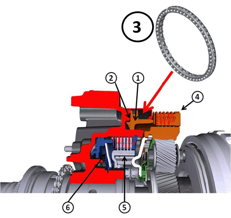
| 1 | Brake B Piston |
| 2 | B1 Chamber |
| 3 | Return Spring |
| 4 | Brake B |
| 5 | Brake A |
| 6 | Return Spring |
Brake B has a spring pack to return the piston into position.
Brake A has a diaphragm return spring.
Clutches
| 1 | Piston |
| 2 | Pressure chamber |
| 3 | Hydraulic compensation chamber |
| 4 | Diaphragm |
| 5 | Diaphragm spring |
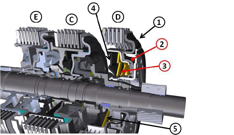
The dynamic pressure of clutches C, D and E is compensated.
The increase in dynamic hydraulic pressure at high speeds is due to the fact that the transmission fluid in the clutch cylinder is subject to considerable centrifugal forces created by the rotation. As a result, the pressure in the clutch cylinder increases in the direction of the maximum radius.
The "dynamic pressure generation" is an undesirable phenomenon because it fruitlessly increases the pressure and obstructs the defined increase or decrease in the pressure chamber.
To ensure the best clutch control even at high speeds, oil is supplied to both sides of the clutch piston, creating a pressure chamber and a pressure compensation chamber.
The transmission fluid in the pressure compensation chamber comes from the lubrication ducts and is therefore at low pressure.
However, once rotating, it is subject to the same dynamic pressure increase due to the centrifugal forces.
In this way, the clutch piston contact pressure is balanced, the shift comfort is significantly improved and safe opening and closing of the clutch is ensured at all speeds.
Brake / Clutch Engagement Matrix
All the gear shifts from the first to the eighth speed and vice versa, are called overlapping engagement/disengagement because during the shift, one clutch must maintain the ability to transmit torque with a reduced pressure, until the other clutch is able to take on the torque.
The gear shift is supported by a brief reduction in torque when shifting up, or a brief increase in torque when shifting down. Thanks to the crossed movements, we can say that the freewheel clutches have been replaced by hydraulic clutch control, with a saving in weight and size.
| GEAR | Brake A | Brake B | Clutch C | Clutch D | Clutch E |
| REVERSE | X | X | X | ||
| 1st | X | X | X | ||
| 2nd | X | X | X | ||
| 3rd | X | X | X | ||
| 4th | X | X | X | ||
| 5th | X | X | X | ||
| 6th | X | X | X | ||
| 7th | X | X | X | ||
| 8th | X | X | X |
| Engaged = X |
Brake/Clutch Engagement Control Solenoid Valves
| GEAR | Brake A | Brake B | Clutch C | Clutch D | Clutch E |
| NEUTRAL | X | X | X | ||
| REVERSE | X | X | X | X | |
| 1st | X | X | X | X | |
| 2nd | X | X | X | X | |
| 3rd | X | X | |||
| 4th | X | X | |||
| 5th | X | X | |||
| 6th | |||||
| 7th | X | X | |||
| 8th | X | X |
| Engaged = X |
Transmission Components
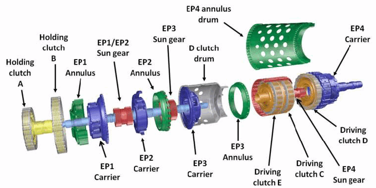
| Holding Clutch : Brake (Engagement Element) |
| Driving Clutch : Clutch (Engagement Element) |
| Annulus : Internal Crown Gear |
| Sun Gear : Sun Gear |
| Carrier : Planetary Carrier |
| Drum : Drum |
1st GEAR
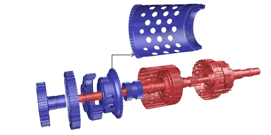
Engagement elements activated: A, B and C Turbine shaft → clutch C → sun gear 4 → planet gears 4 → planet carrier 4.
2nd GEAR
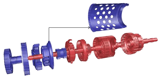
Engagement elements activated: A, B and E Turbine shaft → planet carrier 2 → planet gears 2 → crown gear 2 → clutch E → sun gear 4 → planet gears 4 → planet carrier 4.
3rd GEAR
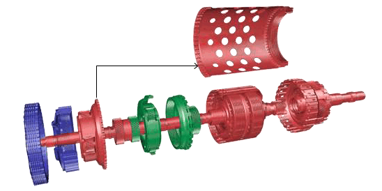
Engagement elements activated: B, C and E.
- Turbine shaft → clutch C → sun gear 4 → planet gears 4 → epicyclic gear train 4.
- Clutch C → clutch E → internal crown gear C2 → planet gears 2 (EP2 is blocked since C2 and PT2 are connected through clutches C and E).
- Turbine shaft → planet carrier 2 (EP2 blocked) → sun gear 1 → planet gear 1 → planet carrier 1 → internal crown gear 4.
The connection from the epicyclic gear train EP1 to the internal crown gear H4 produces a corresponding transmission ratio in the epicyclic gear train EP4 (see force flow in 1st gear).
4th GEAR
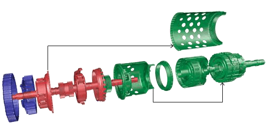
Engagement elements activated: B, D and E.
- Clutch E blocks the epicyclic gear train EP3 and clutch D and EP3 being blocked cause the epicyclic gear train EP4 to be blocked (gear trains 3 and 4 rotate at the same speed = output.
- Turbine shaft → planet carrier 2 → planet gears 2 → sun gears 1 / 2 → planet gears 1 →planet carrier 1 → internal crown gear 4 → planet gears 4 → planet carrier 4.
5th GEAR
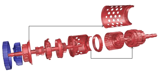
Engagement elements activated: B, C and D.
- Turbine shaft → clutch C → sun gear 4 + internal crown gear 3 (EP2, C2 and S4 = turbine speed).
- Clutch D connect epicyclic gear train 3 to epicyclic gear train 4 (= output shaft).
- Turbine shaft → planet carrier 2 → planet gears 2 → sun gears 1 / 2 → planet gears 1 → planet carrier 1 → internal crown gear 4 → gives a behavior that depends on the speed ratio of S4 (= turbine speed) to C4 with the corresponding speed on PT4.
6th GEAR
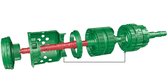
Engagement elements activated: C, D and E.
- Clutches D and E block epicyclic gear trains EP3 and EP4.
- The torque is applied to the epicyclic gear set through clutch C.
- The whole epicyclic gear set rotates at the same speed as the turbine (blocked).
7th GEAR
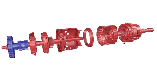
Engagement elements activated: A, C and D
- Turbine shaft → clutch C → sun gear 4 + internal crown gear 3 (= turbine speed).
- Turbine shaft → planet carrier 2 → planet gears 2 → internal crown gear 2 → sun gear 3 → planet gears 3 → planet carrier 3 → clutch D → planet carrier 4.
- Clutch D connects the epicyclic gear train EP3 to planet carrier PT4 (= output shaft).
8th GEAR
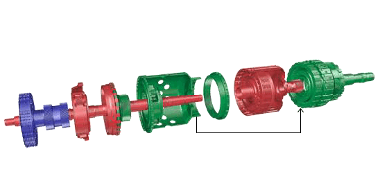
Engagement elements activated: A, D and E.
- Clutch E blocks epicyclic gear train EP3.
- Turbine shaft → planet carrier 2 → planet gears 2 → internal crown gear 2 → epicyclic gear train EP3 (blocked) → clutch D → planet carrier 4.
- Clutch D connects planet carrier 3 to planet carrier 4 (= output shaft).
REVERSE GEAR
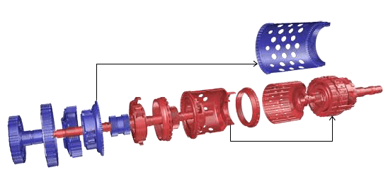
Engagement elements activated: A, B and D.
- Clutch D connects planet carrier 3 to planet carrier 4 (= output shaft).
- Turbine shaft → planet carrier 2 → planet gears 2 → internal crown gear 2 → sun gear 3 → planet gears 3 → planet carrier 3 → clutch D → planet carrier 4.
- Internal crown gear C3 is firmly fixed to sun gear S4.
- S4 drives P4 in the opposite direction to that of the engine.
- Gears P4 roll around fixed C4, rotating PT4 with the transmission ratio indicated, in the opposite direction to that of the engine.
Hydraulic Impulse Solenoid (HIS)
A HIS is installed on the transmission, inserted in the transmission housing close to the mechatronic unit solenoid valves. The HIS provides a hydraulic pressure reserve, to be sent to the mechatronic unit during engine starting due to the Stop & Start function.
The component is used for the Stop & Start function as it allows the gear to be engaged in just 350 milliseconds from starting the engine, so that the driver does not perceive the engagement delay.
The HIS charges when the engine is running, since the pump sends part of the oil to the HIS, in addition to sending it to the mechatronic unit.
HIS (1)
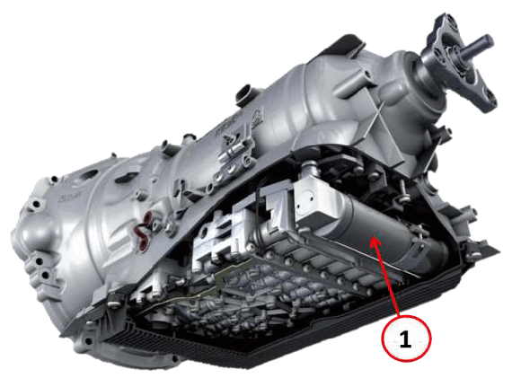
The HIS is fixed to the transmission housing and receives and accumulates about 1 liter of oil sent to it from the transmission oil pump through a connector.
The oil sent to the HIS by the pump, must pass through a regulating valve (8).
The HIS is composed of a piston with a small hole and a spring. During accumulation, the oil only passes through the small hole in the piston.
When the oil enters the HIS, the pressure overcomes the force of the spring (2) and the piston (1) withdraws.
The spring is compressed and allows the piston (1) to withdraw and attach to a blocking point controlled by a solenoid valve.
If the HIS is powered or the oil pump is operating, the piston will remain blocked.
During Start & Stop operation, namely when the engine is off, the HIS is powered in order to keep the piston blocked, even when the oil is no longer being pumped.
When the vehicle is restarted, the HIS will no longer be powered and the spring will be able push the piston, which will send the oil under pressure to the mechatronic unit to engage the gear.
When the piston pushes the oil, the regulating valve spring compresses, opening the valve fully to allow the oil at the HIS outlet to pass.