Description And Operation
DESCRIPTION
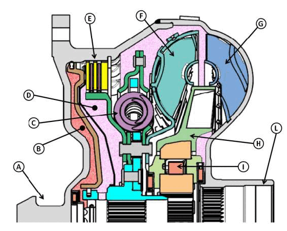
| A - Torque Converter Front Hub |
| B - Converter Clutch Chamber |
| C - Damper |
| D - Turbine and Pump Chamber |
| E - Torque Converter Clutch |
| F - Turbine |
| G - Pump |
| H - Stator |
| I - Stator One-Way Clutch |
| L - Transmission Pump Drive Hub Groove |
The torque converter must be replaced if a transmission failure resulted in large amounts of metal or fiber contamination in the fluid.
- The torque converter is essential to allow the vehicle to drive off and operates according to the dynamic fluid coupling principle. This means that there is a difference between the rotation speed of the pump and that of the turbine. This different in rotation speed is called converter slippage and reduces the efficiency of the fluid coupling.
- The torque converter installed is of the so-called "three-duct" type. With this architecture, the turbine area is supplied by two ducts, while the converter clutch is controlled by a separate third duct.
- The converter lock-up clutch eliminates the converter slippage, thereby reducing fuel consumption. Moreover, opening and closing of the lock-up clutch is adjusted according the desired driving comfort. The converter lock-up clutch is of the multi-plate type and is managed by the TCM. It consists of 2 clutch plates and 3 steel discs, thereby creating 4 friction surfaces. The high friction coefficient and the number of friction surfaces has allowed the operating range of the lock-up clutch to be extended considerably, improving the overall efficiency of the kinematic chain. There are turbine torsional dampers inside the torque converter to effectively dampen the engine's torsional vibrations when the lock-up clutch is activated.
- The torque converter clutch opens and closes independently and separately from the turbine area, giving advantages in the torque converter clutch control.
- Thanks to the special construction and control characteristics, the TCM is able to open and close the lock-up clutch over a wide engine operating range, from first gear up to eighth gear, according to the detected driving conditions and the active shifting strategy.
- The lock-up clutch pressure is controlled by the TCM through the EDS-LuK solenoid valve (converter clutch adjustment solenoid valve) and the corresponding hydraulic control valves.
OPERATION
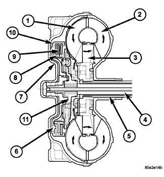
| 1 - TURBINE |
| 2 - IMPELLER |
| 3 - STATOR |
| 4 - INPUT SHAFT |
| 5 - STATOR SHAFT |
| 6 - PISTON |
| 7 - COVER SHELL |
| 8 - INTERNALLY TOOTHED DISC CARRIER |
| 9 - CLUTCH PLATE SET |
| 10 - EXTERNALLY TOOTHED DISC CARRIER |
| 11 - TURBINE DAMPER |
The torque converter housing has a unique shape to incorporate the Torque Converter Clutch (TCC) and flex plate connection. The torque converter uses the typical turbine, impeller and stator assemblies found in a standard torque converter assembly. The torque converter drives the pump through the splines on the inside of the hub. The torque converter uses a multi-disc torque converter clutch system that improves the durability and the holding pressure in the lock-up circuit. The torque converter incorporates a turbine dampening system. This system suppresses torsional vibrations from the engine to ensure optimal shift quality and reduce noise and vibration concerns.
TCC RELEASE When the TCC is open, the TCC piston is pushed to its default position by torque converter chamber pressure. The Torque Converter Switch Valve (SV-TC) provides pressure for torque converter operation which has been regulated by the Torque Converter Pressure Regulating Valve (TC-V). After exiting the torque converter, fluid moves into the cooling and lubrication circuits. The converter pressure retention valve (TCH1-V) ensures the torque converter pressure is a minimum of 0.35 bar (5 psi) when the TCC is open.
TCC APPLY When the TCC solenoid is energized, fluid is directed to the torque converter switch valve (SV-TC) and TCC lockup valve (TCC-V). The TCC lockup valve directs fluid to the TCC and torque converter chamber. The torque converter switch valve directs fluid exiting the converter chamber to a secondary pressure retention valve (TCH2-V) which is calibrated to retain 1.0 bar (14.5 psi) of pressure in the converter. The torque converter switch valve also directs line pressure to the cooler and lubrication circuit.