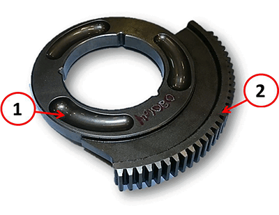
Description And Operation
DESCRIPTION
| 1 | Drivetrain Control Module (DTCM) |
| 2 | Transfer Case |
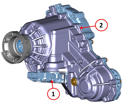
The DTCM is installed on the transfer case, which also includes the control actuator to transfer the torque to the front axle.
OPERATION
| 1 | Transfer case |
| 2 | Input Shaft |
| 3 | Output Shaft |
| 4 | DTCM |
| 5 | Worm Gear |
| 6 | Idler Gear |
| 7 | Ramp Drive Ring |
| 8 | Case Housing and Clutch Plates |
| 9 | Chain |
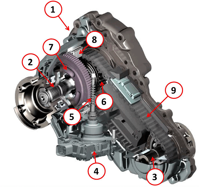
- The transfer case is supplied by MAGNA.
- Two aluminum shells enclose the input shaft, the output shaft and the parts needed to transfer the torque to the front axle.
- The torque is transferred to the front axle as the two shafts have sprockets united by a chain.
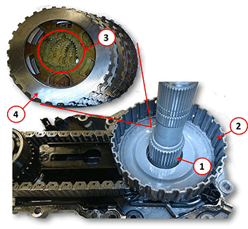
- The sprocket on the input shaft is idle and fixed to the clutch plate bell housing.
- When the clutch plates are closed, controlled by the DTCM, the idler wheel is connected to the input shaft because the clutch plates are fixed to the input shaft when the steel discs, interposed between the clutch plates, are fixed to the bell housing.
| 1 | Clutch Bell Housing |
| 2 | Lower Ram Drive Ring |
| 3 | Chain |
| 4 | Sprocket |
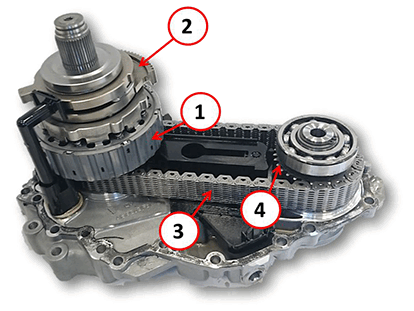
When engagement of front axle traction is requested, the control module commands the actuator that will drive a system of ramps and balls to close the clutch pack to connect the input shaft to the idler wheel, which can thereby transmit the torque to the output shaft.
| 1 | Input Shaft |
| 2 | Bell Housing |
| 3 | Clutch Plate Input Shaft Splines |
| 4 | Steel Plates |
- The gear ratios are different between the front axle and the rear axle. The difference in rotation speed between the two axles is dissipated by the clutch plates slipping. This feature is called "overslip". The maximum overslip that can be achieved is 2.5%.
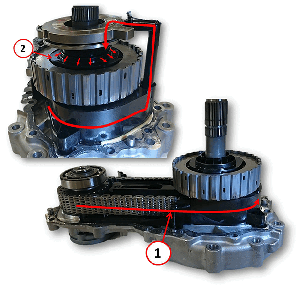
- Because of the overslip, the clutch plates must be continuously lubricated. As the chain moves, it transfers a quantity of oil by means of a plastic conveyor, delivering it to the plates and preventing them from being damaged by overheating.
- The conveyor allows the oil to reach a distributor, made of plastic, which is fastened to the input shaft and located inside the bell housing. The distributor's rotation distributes the oil homogeneously inside the bell housing and therefore to the plates.
| 1 | Oil Flow |
| 2 | Oil Distributor |
System Of Ramps And Balls
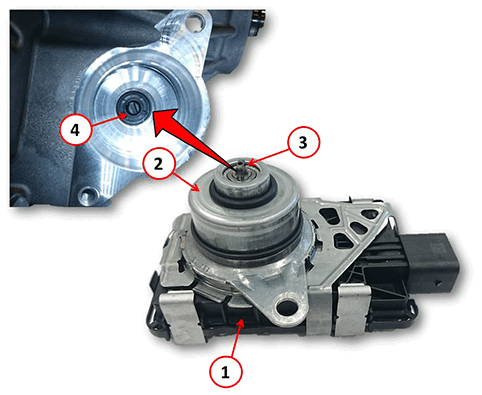
The DTCM has a built-in electric motor, which turns on command. When the motor turns, it moves the worm gear that enters through the transfer case shell.
| 1 | Drive Train Control Module (DTCM) |
| 2 | Electric Motor |
| 3 | Worm Gear Drive Shaft |
| 4 | Worm Gear Screw |
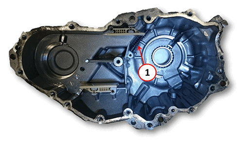
| 1 | Worm Gear Screw |
| 1 | Bearing |
| 2 | Upper Ramp Drive Ring |
| 3 | Ball Bearing |
| 4 | Worm Gear Teeth |
| 5 | Clutch Pressure Plate |
| 6 | Springs |
| 7 | Upper Ring Splines to Transfer Case |
| 8 | Oil Conveyor |
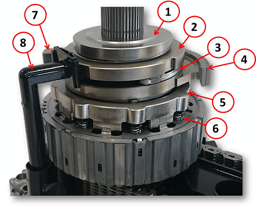
The worm gear only contacts the lower ramp drive ring, while the upper ring cannot turn because it is fixed to the transfer case shell. When the worm gear rotates, it moves the two ramp drive rings.
The balls are interposed between the two rings. As they slide along the ramps, the balls transform the rotary movement of the input ring into an axial movement of the output ring.
The axial movement of the output ring compresses the clutch pack.
| 1 | Lower ring rotation |
| 2 | Lower ring movement |
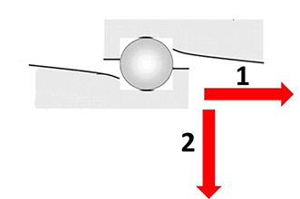
Clutch Drive Pack Components
Upper Ramp Drive Ring
| 1 | Ball Bearing |
| 2 | Balls |
| 3 | Upper Ring Ramps |
| 4 | Upper Ring Locking Tooth |
| 5 | Oil Conveyor |
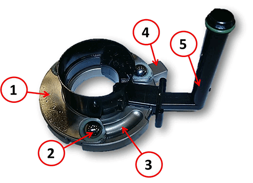
Lower Ramp Drive Ring
| 1 | Lower Ring Ramps |
| 2 | Worm Gear Teeth |