Exterior Lamps And Lighting
The exterior lamps and lighting system is managed by the Body Control Module (BCM).
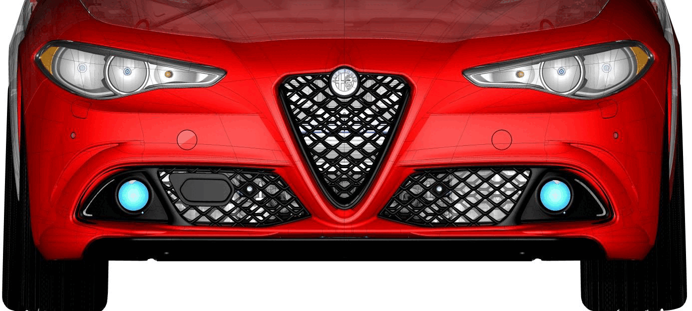
FRONT EXTERIOR LAMPS AND LIGHTING
Three range levels of headlamp units are available:
- Basic
- Mid Level
- Premium or Top Level
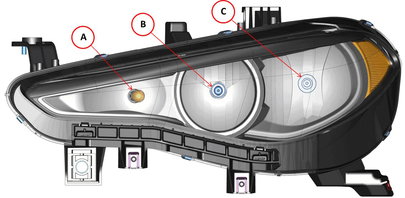
Basic Level
- A - Direction indicator (PY24W bulb)
- B - High Beam / Daytime Running Lamp (DRL) / Side Marker Lamp (H15 two-filament halogen bulb)
- C - Low Beam (H7 halogen bulb
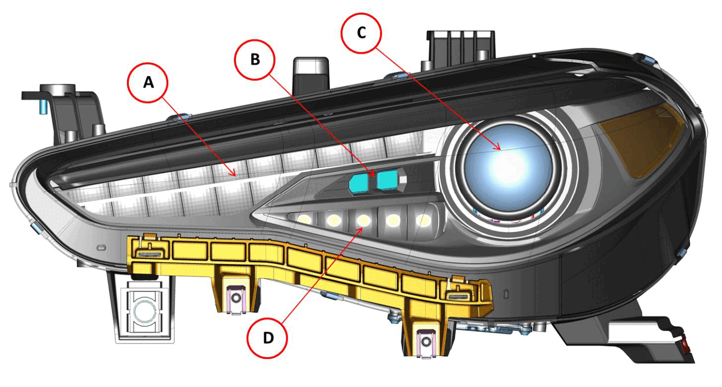
Mid Level
- A - DRL / Side Marker (LED)
- B - Static Bending Lamp (SBL) (LED)
- C - High/Low Beam Lamp (Xenon 25W D5S ECE bulb)
- D - Direction Indicator (LED)
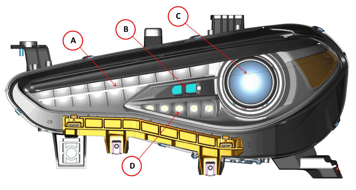
Premium / Top Level
- A - DRL/Side Marker Lamp (LED)
- B - SBL - (LED)
- C - High / Low beam (Xenon 35W D3S ECE bulb)
- D - Direction indicator (LED)
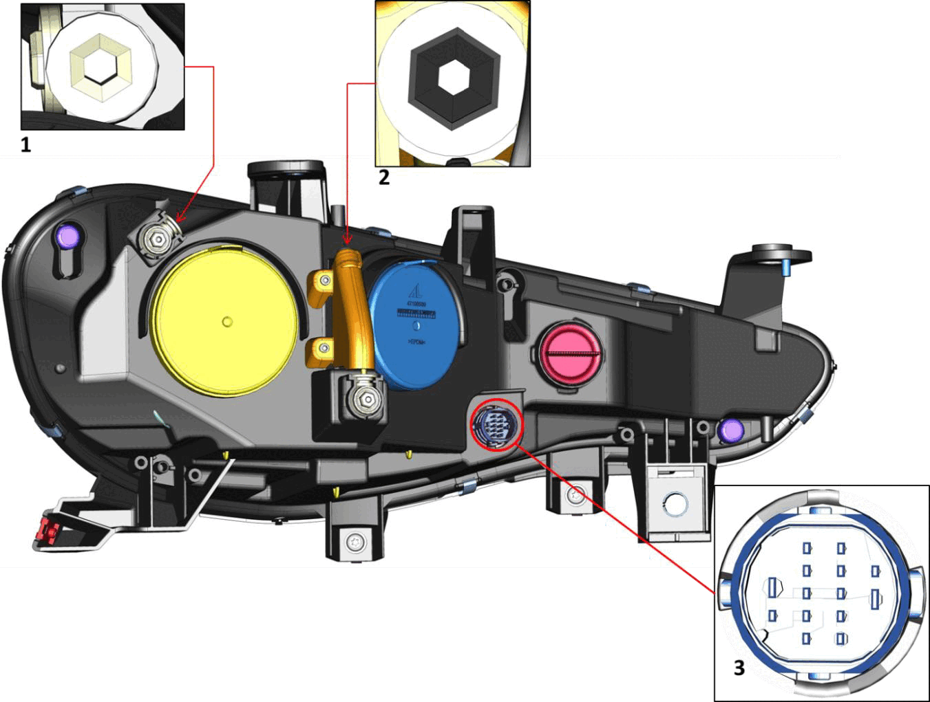
BASIC LEVEL
- 1 - Horizontal adjustment hexagonal screw
- 2 - Vertical adjustment hexagonal screw
- 3 - Headlamp wiring harness connector
With basic level headlamps, the BCM activates the function in its proxy. It is worth noting that the cornering function is performed by the BCM when the low beams are on, the steering is turned by a given angle and the vehicle speed is slower than 40 km/h (25 mph). In these conditions, the BCM activates the front fog lamp on the side towards which the steering is turned.
On mid and top level headlamps there are two Light Emitting Diodes (LEDs) for managing the Static Bending Lamp (SBL) operation. The objective is to illuminate the zones which are normally not reached by the low beam headlamps.
On a bend with a radius under a given threshold, the low beam headlamp cannot appropriately cover the side zone of the road (inside the bend) even in presence of adaptive headlamps. The presence of the SBL LEDs allows illumination in this dark area better.
The LEDs are activated in the following conditions:
- Vehicle speed = 20 km/h (13 mph)
- Steering radius ? 500 m
- low beams on or "Auto" function on
The cornering function is not available on mid and top level headlamps.
The mid level headlamp has a 25W Xenon bulb for the high beam/low beam function. The user can adjust the bulb in the vertical direction using the knob in the exterior lamp.
The top level headlamps are equipped with 35W Xenon bulbs (high beam/low beam). The top level headlamp also implements the Adaptive Front lighting System (AFLS) function managed by the AFLS module for laterally adjusting the light beam according to the steering angle.
The Lane Departure Warning (LDW) system, if equipped, is integrated in the Smart Beam function which automatically switches from high beam to low beam when crossing the light beam of a vehicle approaching in the opposite direction.
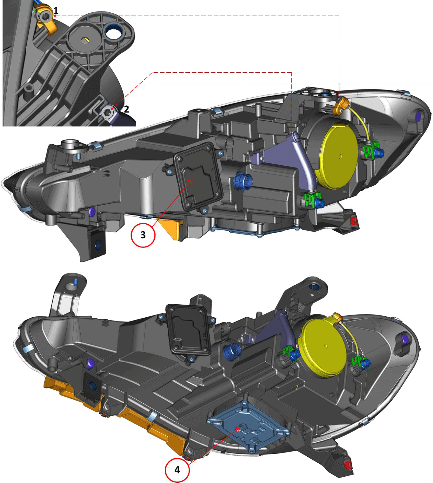
- 1 - Horizontal adjustment hexagonal screw
- 2 - Vertical adjustment hexagonal screw
- 3 - HID Ballast control unit (Xenon 35W) HDU
- 4 - DRL/side marker lamp LED control unit
The HDU control unit (on both right and left headlamps) activates the Xenon ballast.
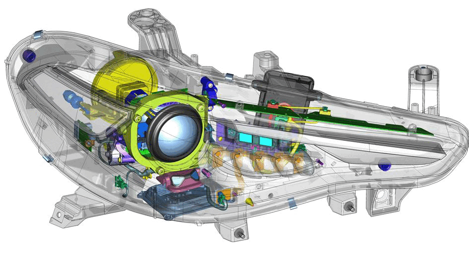
The DRL/side marker lamp control unit performs the following functions:
- Activating the DRL LEDs
- Activating the SBL LEDs.
- Activating the direction indicators.
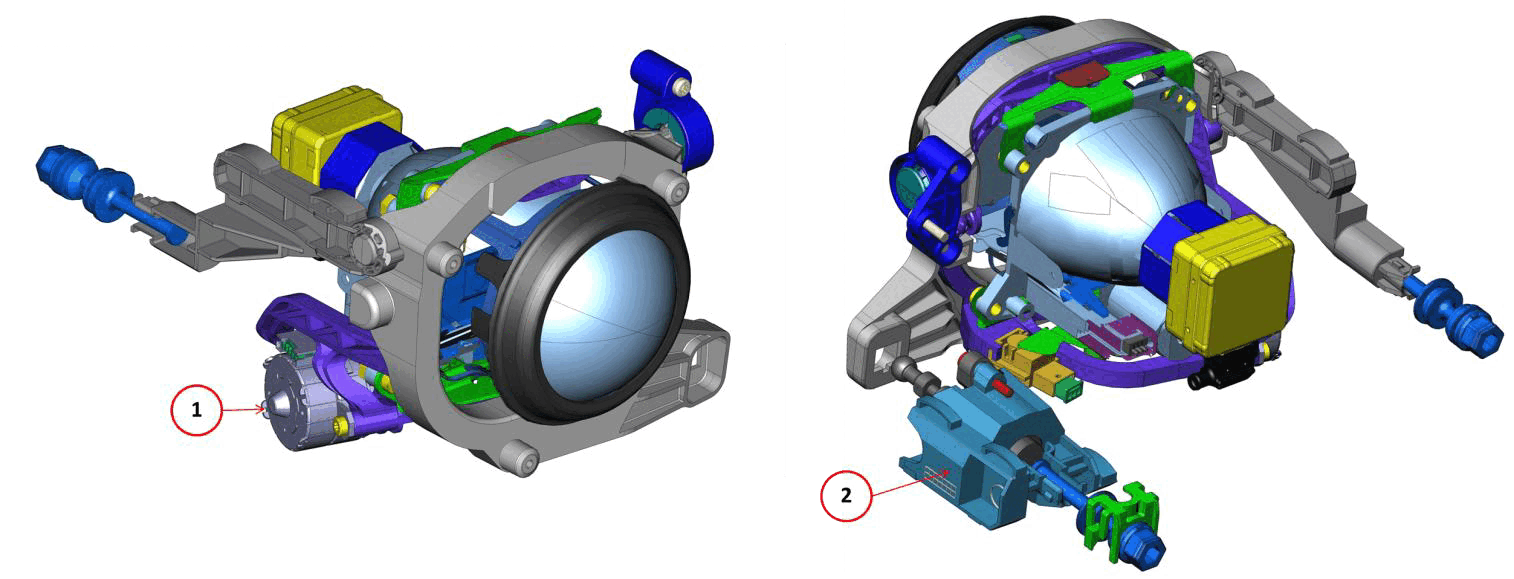
HORIZONTAL AND VERTICAL ADJUSTMENT RECOVERY SOLUTIONS
The following recovering conditions are provided in case of faults to the vertical and horizontal adjustment motors:
- If the vertical adjustment motor (2) is blocked, the headlamp will be turned all rightwards by the horizontal movement motor (1).
- If the horizontal adjustment motor is blocked, the headlamp will be turned downwards (all down) by the vertical movement motor.
- If both motors are blocked, the headlamp will be blocked in its current position but will not be switched off.
The headlamp will be locked in the current position due to LIN faults.
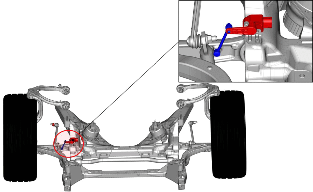
FRONT AXLE LEVELING SENSOR LOCATION
The AFLS directly detects the suspension position by means of the one front axle sensor. According to axle sensor signal, AFLS instructs (via LIN buse) the (right and left) lateral adjustment motors to laterally adjust the headlamps and change their position. The AFLS is the master while the two control units are the slave. The AFLS receives the steering angle and vehicle speed parameters via Controller Area Network (CAN) and instructs the control units which manage the (right and left) lateral movement to implement the appropriate adjustment allow the beam to follow the bend.
The functions at which the Xenon headlamps are operated are:
- Key status: ON
- Rev counter: >500 rpm
- Exterior lights: low beam function
- Reverse gear: Not engaged.
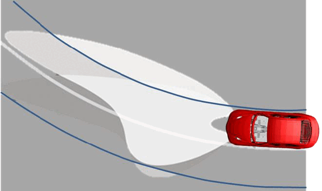
When this conditions occurs, the AFLS starts performing the horizontal adjustment of the Xenon lights when the vehicle speed is: ?5 km/h
The AFLS module modifies its sensitivity level and reactivity according to vehicle speed and bend radius. The AFLS implements 4 sensitivity levels:
- 1. Very close level: for speeds in the 0km/h - 5km/h (3 mph) range; bends of 6m-20m (parking maneuvers)
- 2. Close level: for speeds in the 5km/h - 50km/h (3 - 31 mph)range; bends of 10m-50m (driving in cities)
- 3. Medium level: for speeds in the 50km/h-100km/h (31 - 62 mph) range; bends of 40m-300m (extra-urban driving)
- 4. Distant level: speed ?100km/h (62 mph); bends of 250m-500m (motorways)
The four sensitivity levels of the AFLS allow the unit to calculate the right speed for turning the Xenon headlamps horizontally so as to follow the correct bending of the road without dark shadows.
The BCM instructs the DRL (right and left) control units to activate the direction indicator, DRL and SBL LEDs.
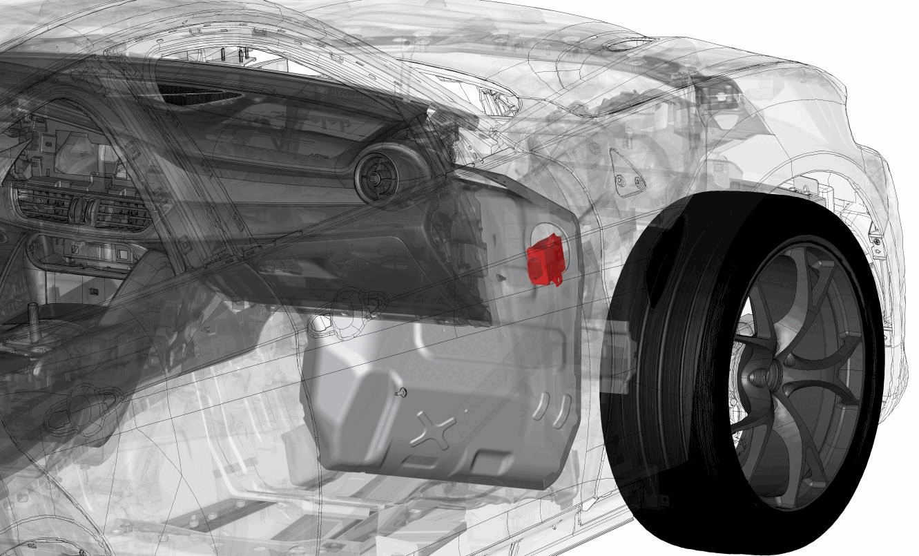
AFLS MODULE - To service the module. Refer to MODULE, ADAPTIVE FRONT LIGHTING SYSTEM (AFLS), REMOVAL AND INSTALLATION . When the AFLS module is replaced, the diagnostic scan tool needs to be used to calibrate the AFLS. Using the scan tool, select the AFLS and then the "Misc Functions" menu. Select and start the "AFLS Calibration" routine. Follow the on-screen instruction to complete this procedure.
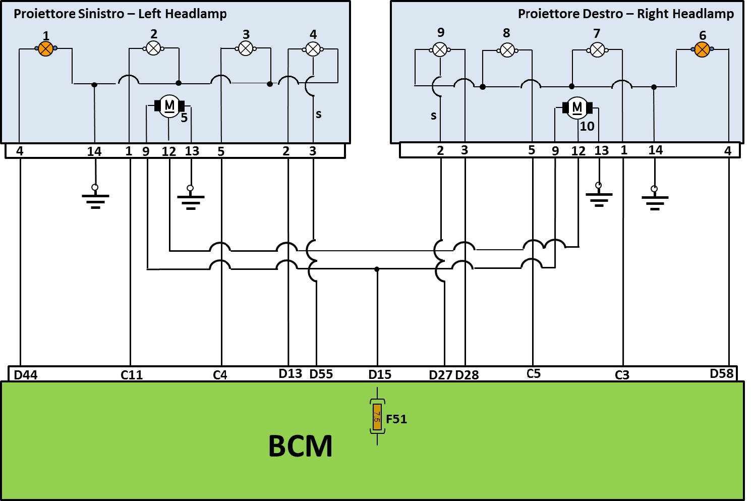
| 1 - Left direction Indicator | 6 - Right Direction Indicator |
| 2 - Left Low Beam | 7 - Right Low Beam |
| 3 - Left High Beam | 8 - Right High Beam |
| 4 - Left DRL/Side Marker Lamp | 9 - Right DRL/Side Marker Lamp |
| 5 - Vertical Lamp socket Adjustment Motor (left headlamp) | 10 - Vertical Lamp socket Adjustment Motor (right headlamp) |
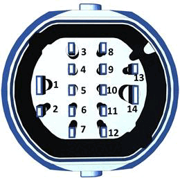
| 1 - Low beam positive control | 8 - NA. |
| 2 - DRL/side Marker Lamp Positive Control | 9 - Vertical Adjustment Motor Positive Control |
| 3 - DRL/side Marker Lamp Signal | 10 - NA. |
| 4 - Direction Indicator Lamp Positive Control | 11 - NA. |
| 5 - High Beam Positive Control | 12 - Vertical Adjustment Motor Signal |
| 6 - NA. | 13 - Ground |
| 7 - NA. | 14 - Ground |
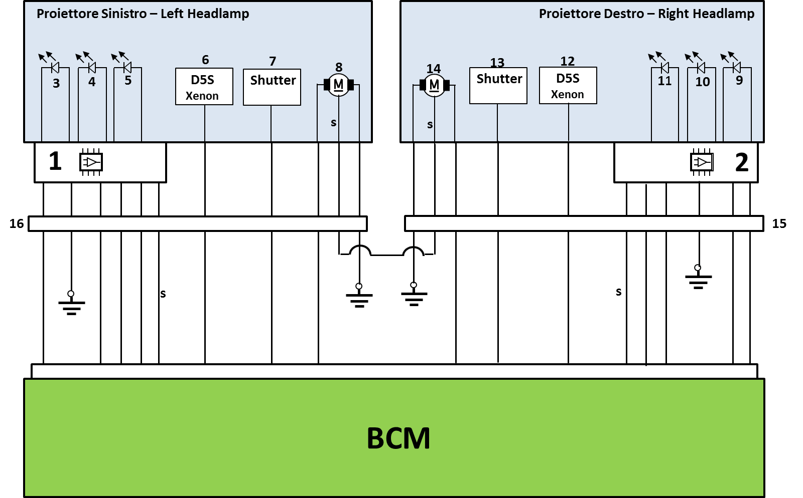
| 1 - DRL/Side Marker Lamp LED Control Unit (left headlamp) | 9 - Right Direction indicator LED Lamp |
| 2 - DRL/Side Marker Lamp LED Control Unit (right headlamp) | 10 - Right SBL LED |
| 3 - Left Direction indicator LED Lamp | 11 - Right DRL/Side Marker LED Lamp |
| 4 - Left SBL LED | 12 - D5S 25w Bulb |
| 5 - Left DRL/Side Marker LED Lamp | 13 - Shutter for High/Low Beam Changes |
| 6 - D5S 25W Bulb | 14 - Right Vertical Bulb Socket Electronic Adjustment Motor |
| 7 - Shutter for High/Low Beam Changes | 15 - Right Lamp Connector |
| 8 - Left Vertical Bulb Socket Electronic Adjustment Motor | 16 - Left Lamp Connector |
In mid level headlamps there is only the DRL/side light LED control unit which receives inputs directly from the BCM, which sends current to the direction indicator, SBL and DRL/side marker lamp LEDs accordingly.
The Xenon D5S 25W bulb and the vertical adjustment motor are controlled directly by the BCM.
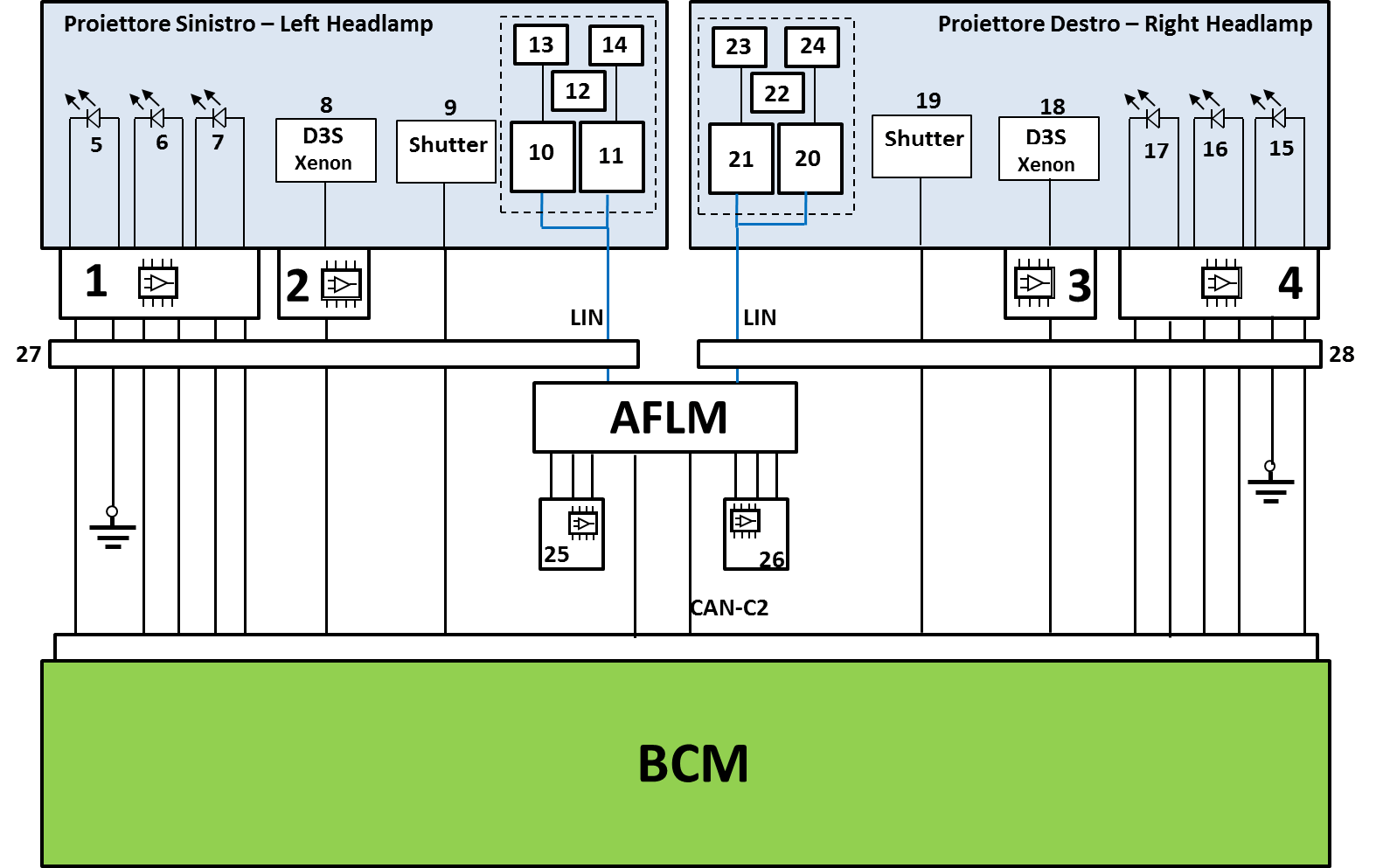
| 1 - DRL/Side Marker Lamp LED Control Unit (left headlamp) | 9 - Shutter for High/Low Beam Changes | 17 - Right DRL/Side Marker LED Lamp | 25 - Right Front Position Sensor |
| 2 - Left Headlamp HDU (LHDU) | 10 - AFS Adaptive Headlamp Module | 18 - Xenon 35W D3S Bulb | 26 - Left Rear Position Sensor |
| 3 - Right Headlamp HDU (RHDU) | 11 - Vertical Movement Module | 19 - Shutter for High/Low Beam Changes | 27 - Left Headlamp Connector |
| 4 - DRL/Side Marker Lamp LED Control Unit (right headlamp) | 12 - headlamp Horizontal Position Sensor (left) | 20 - Adaptive Headlamp Module | 28 - Right Headlamp Connector |
| 5 - Left Direction Indicator LED Lamp | 13 - Horizontal Movement Motor | 21 - Vertical Movement Module | Adaptive Front Lighting Module (AFLS) |
| 6 - Left SBL LED | 14 - Vertical Movement Motor | 22 - Headlamp Position Sensor (left) | |
| 7 - Left DRL/Side Marker LED Lamp | 15 - Right Direction indicator LED Lamp | 23 - Horizontal Movement Motor | |
| 8 - Xenon 35W D3S Bulb | 16 - Right SBL LED | 24 - Vertical Movement Motor |
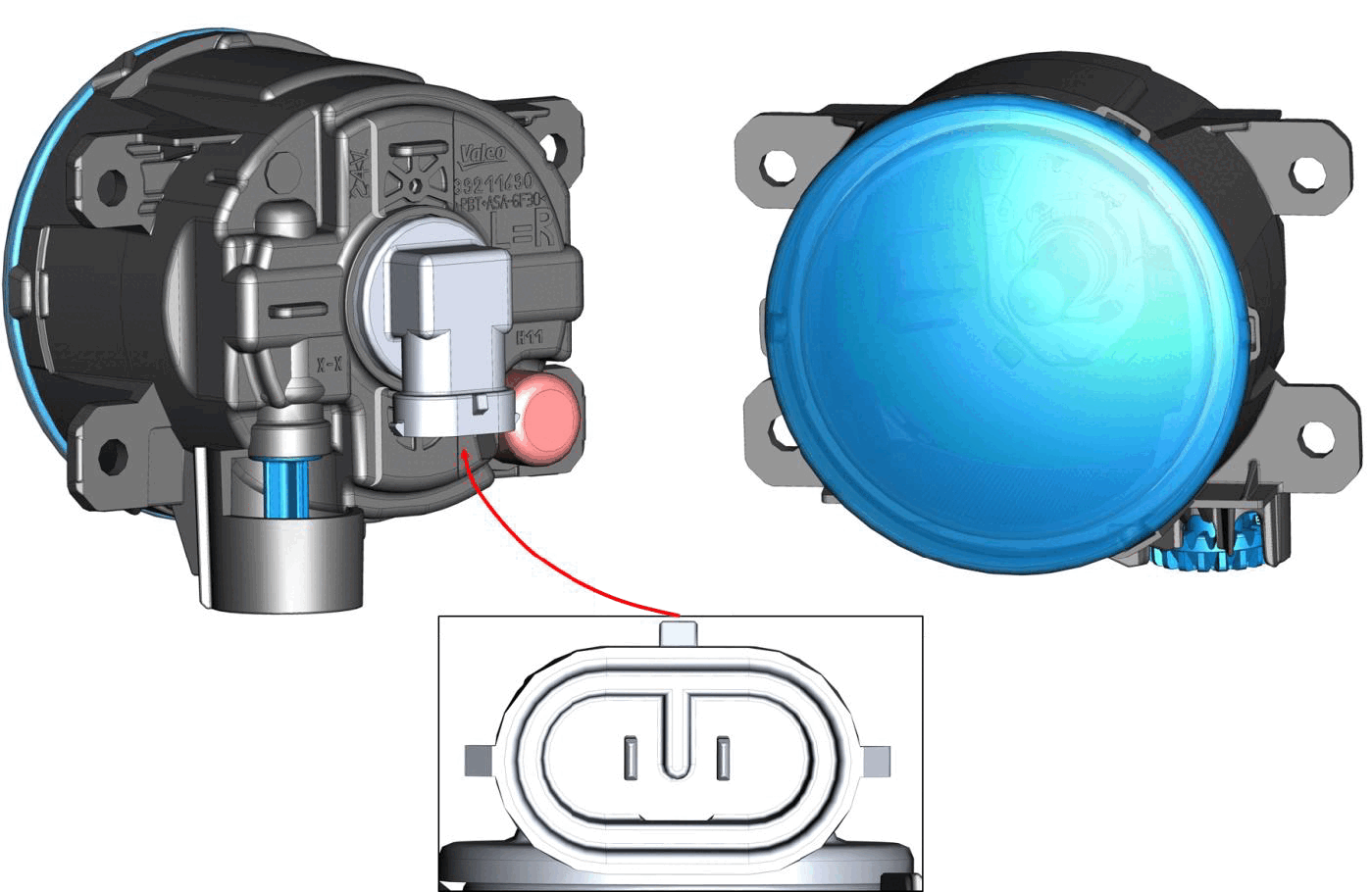
FRONT FOG LAMPS
The front fog lights are available on all versions, except for Quadrifoglio. The fog lights are not compatible with mid or top level headlamps because of the presence of SBL LEDs. The fog lights are powered directly by the BCM.
The fog lights are adjusted manually by inserting a screwdriver or a similar tool in the hole in the bottom of the fog lights themselves.
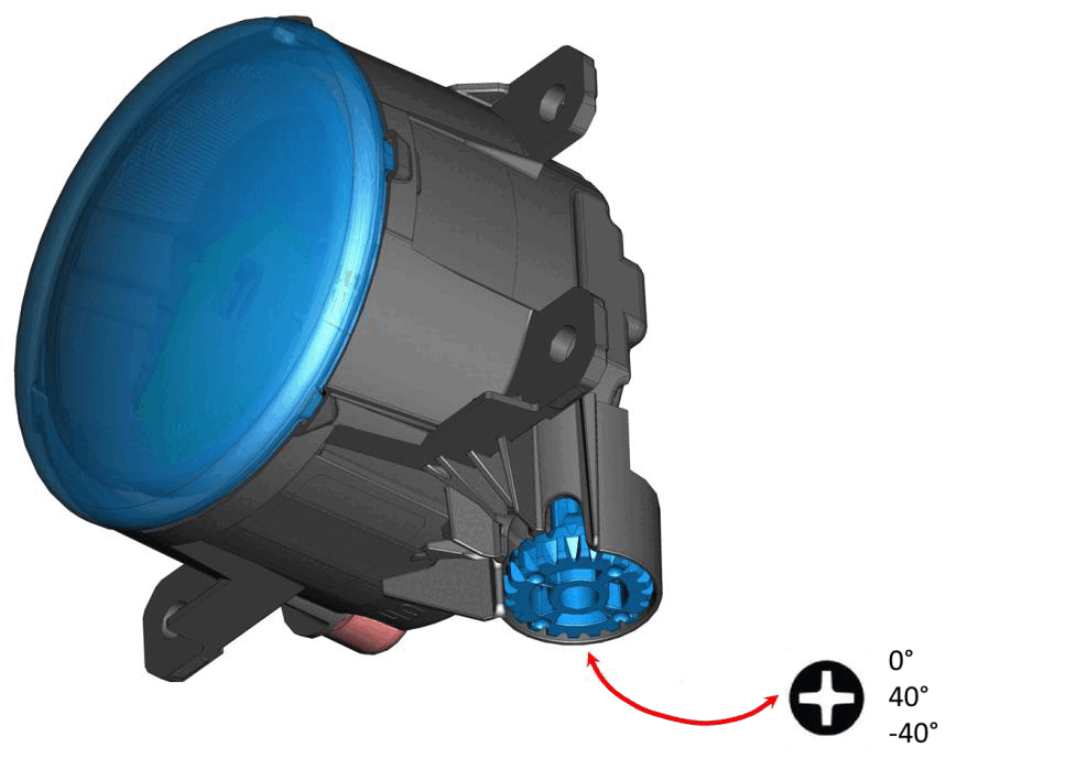
The fog lamp bulbs specification type is H11.
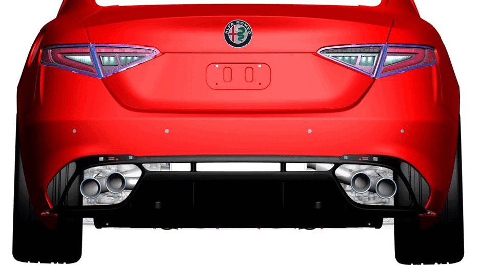
REAR EXTERIOR LAMPS AND LIGHTING
The rear tail lamps use LEDs only. The rear tail lamps clusters consists of a inboard part and an outboard tail lamp.
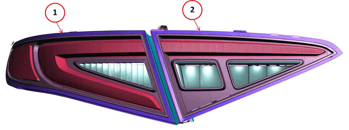
The inboard tail lamp (1) and the outboard tail lamp (2) are secured to the vehicle by snap fittings (no screws).
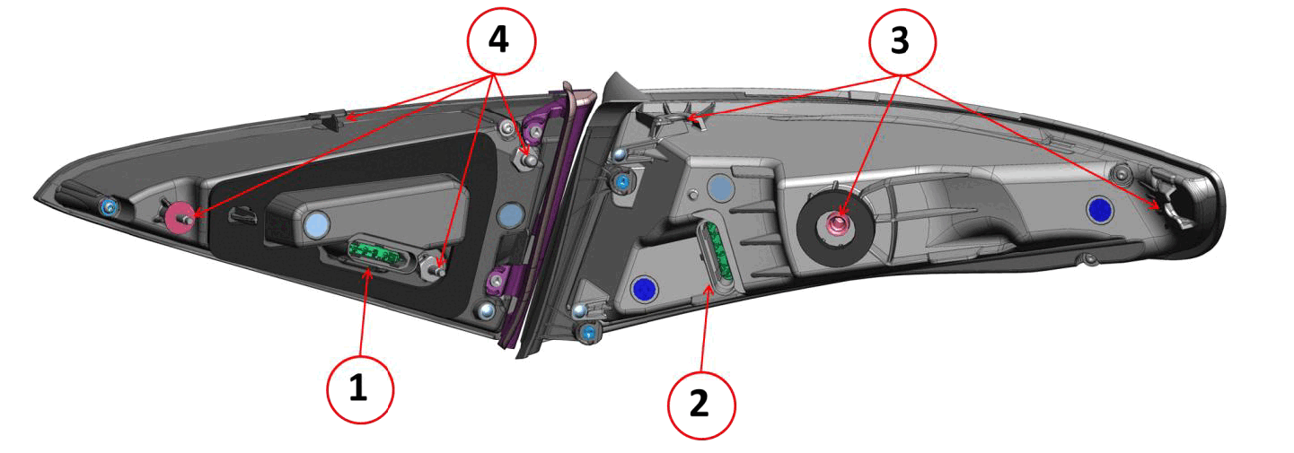
- 1 - Outboard tail lamp electrical connector
- 2 - Inboard tail lamp electric connector
- 3 - Inboard tail lamp retaining points
- 4 - Outboard tail lamp retaining points
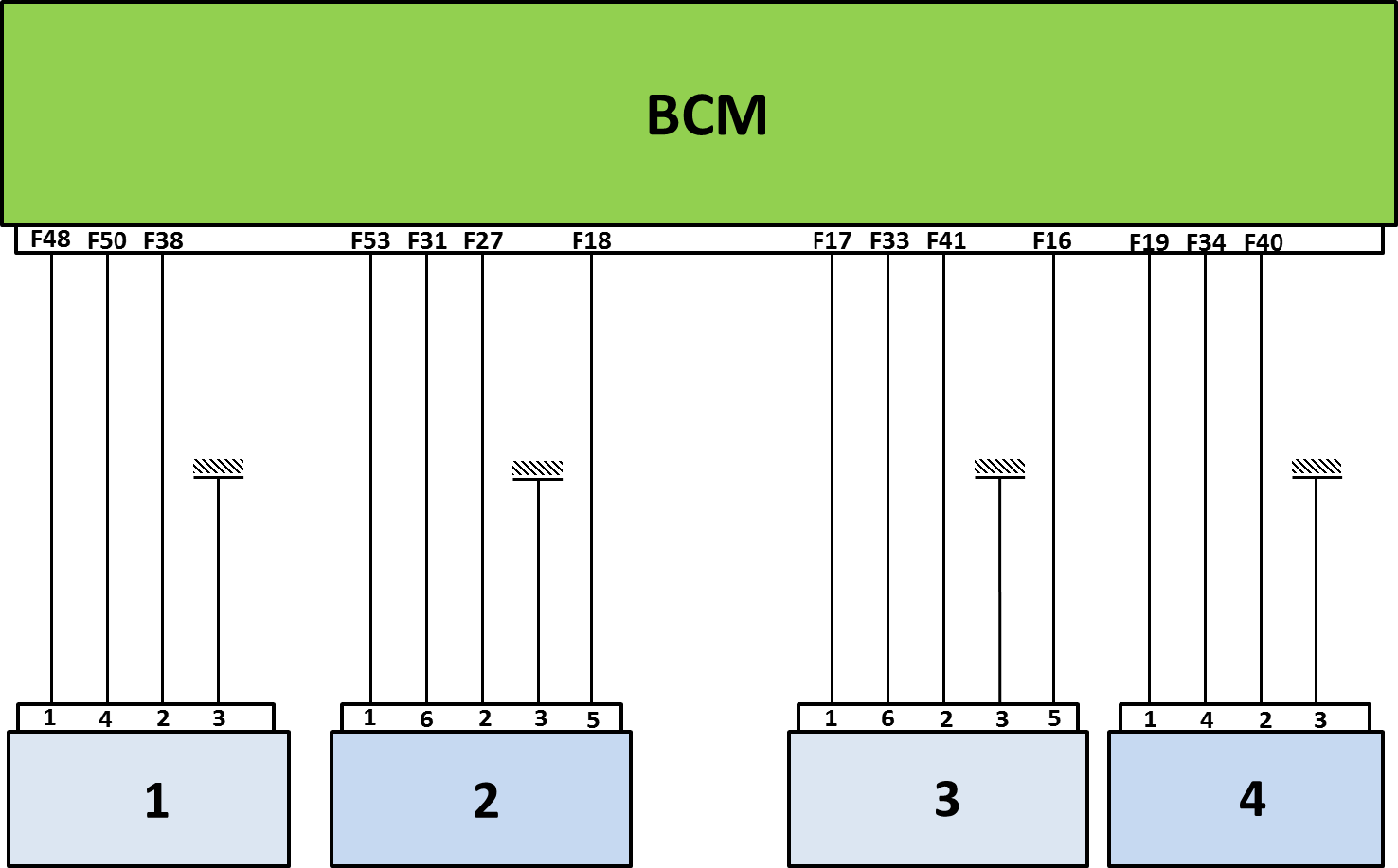
Rear exterior lamps and lighting wiring diagram
- 1 - Outer left rear lamp
- 2 - Inner left rear lamp
- 3 - Inner right rear lamp
- 4 - Outer right rear lamp
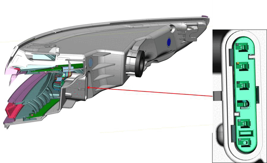
| Pin | Description |
|---|---|
| 1 | Tail lamp/Brake Lamp |
| 2 | Tail lamp/Brake Lamp (Diagonal LEDs) |
| 3 | Ground |
| 4 | Direction Indicator |
| 5 | NA |
| 6 | NA |
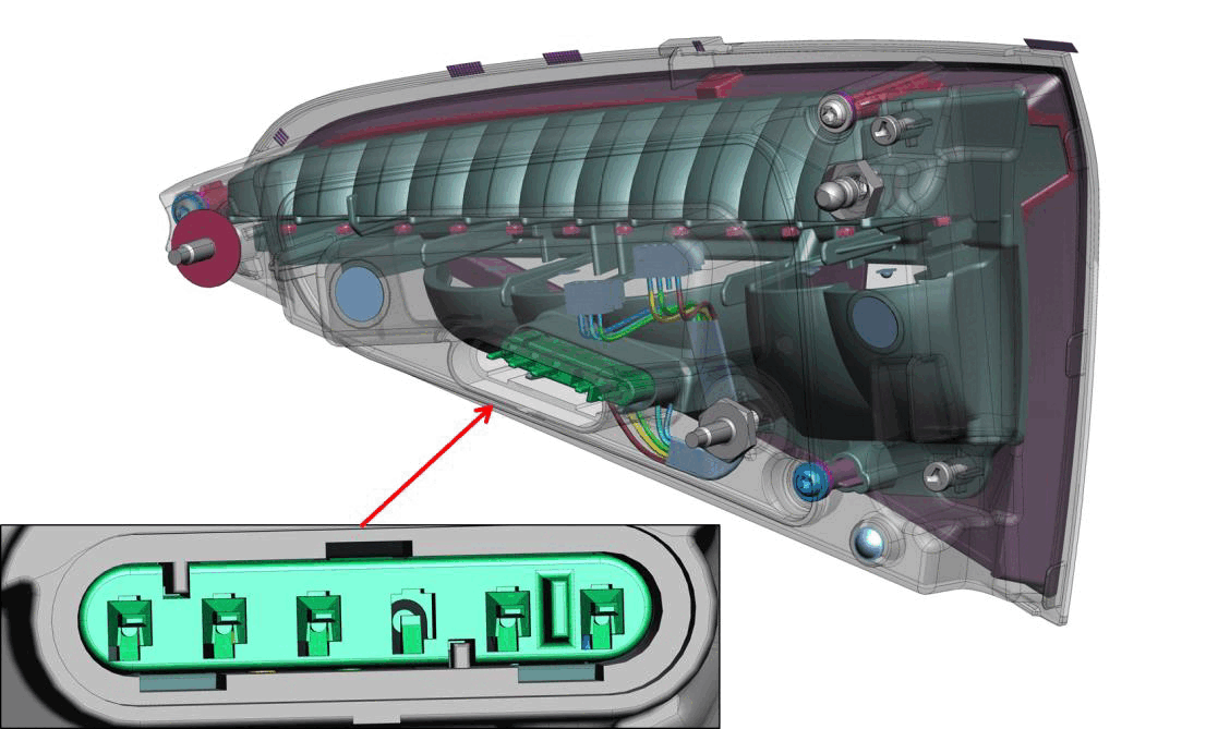
| PIN | DESCRIPTION |
|---|---|
| 1 | Tail Lamp/Brake Lamp |
| 2 | Tail Lamp/Brake Lamp (Diagonal LEDs) |
| 3 | Ground |
| 4 | NA |
| 5 | Fog Lamps (not equipped) |
| 6 | Reverse Lamp |
The traditional brake pedal switch is missing from the pedal assembly. The pedal pressed signal is detected by the ESC module which detects the pressure in the braking circuit.
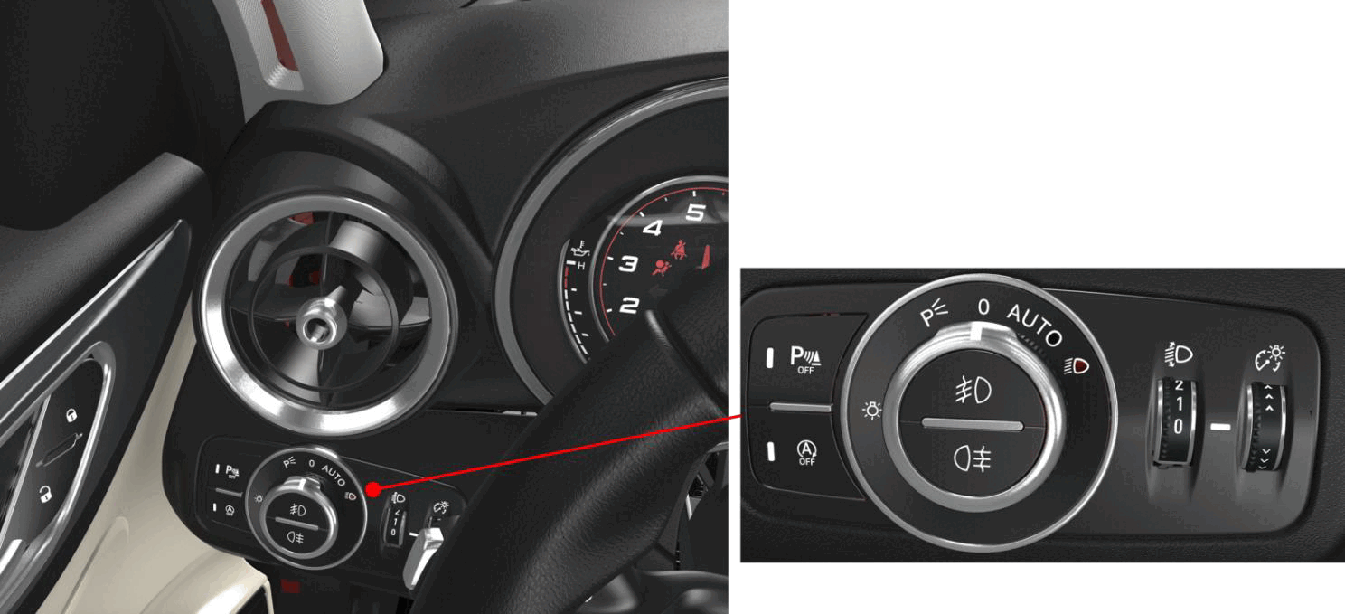
HEADLAMP CONTROL SWITCH
The headlamp control switch panel is integrated to the instrument panel on driver's side which also includes the Electronic Stop Start (ESS) (if equipped) and front Park Assistance System (PAS) sensor ON/OFF switches. The switch is connected to the BCM. The headlamp control switch panel configuration depends on the trim level of the vehicle.
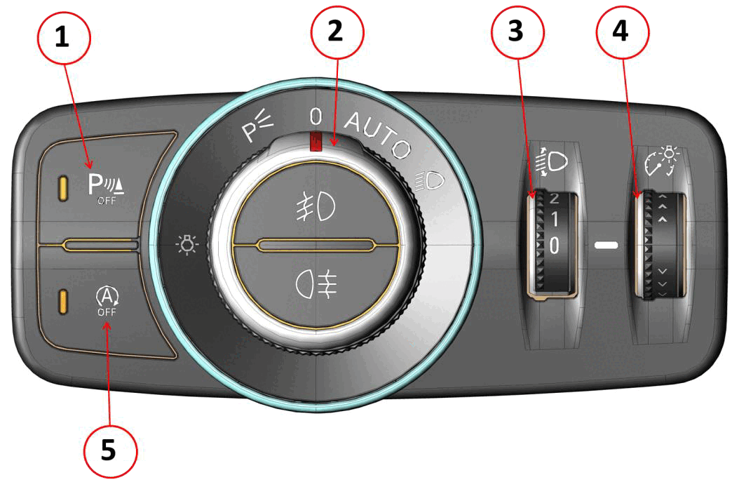
- 1 - Front PAS ON/OFF switch
- 2 - Exterior lamps control knob
- 3 - High beam/low beam adjustment knob
- 4 - Passenger compartment interior backlight dimming knob
- 5 - ESS ON/OFF switch
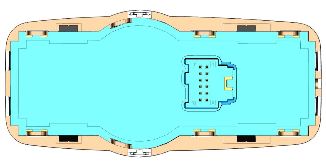
| PIN | Description |
|---|---|
| 1 | Key-ON Fused Power |
| 2 | Dashboard Backlight Control |
| 3 | NA |
| 4 | Exterior Lights Signal |
| 5 | Front Fog Lamp Signal |
| 6 | NA |
| 7 | Dimming Knob |
| 8 | ESS Switch |
| 9 | ESS Switch LED |
| 10 | NA |
| 11 | Front PAS Switch LED |
| 12 | Ground |