Blind Spot Monitor System
The Blind Sport Monitoring system can help the driver to avoid accidents by providing visual warnings. In all cases, the system does not replace the driver and cannot correct dangerous driving styles. The driver must remain alert and in control of the vehicle at all times.
DESCRIPTION
BLIND SPOT MONITORING AND REAR CROSS PATH DETECTION SYSTEMS
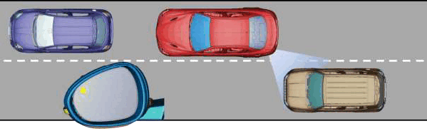
BLIND SPOT MONITORING (BSM)
The system continuously monitors the rear blind spots on both sides of the vehicle when any forward gear is engaged and the speed is higher than approximately 10 km/h (6 mph).
The system uses two radar modules installed behind the rear bumper in side area to inform the driver of vehicles/objects present in these areas by means of specific warning icons installed on each wing mirror.
The blind spot detection system switches into standby mode if:
- With manual gearbox, the parking brake applied.
- With automatic transmission, PARKING position is engaged.
BSM SYSTEM FUNCTION OVERVIEW
:
- Monitors the vehicle's blind spots and warns the driver when another vehicle is present
- It uses dual broadband radar sensors located behind the rear side panels
- It operates the icons on the wing mirrors
- Notifies the presence of vehicles in the blind spots when the lane is changed or other vehicles are overtaking
- Notifies the detection of vehicles moving in the rear area transversely to the vehicle, when this is reversing
- The driver can activate / deactivate the system and select the function mode via the radio menu
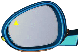
Detection conditions:
- Vehicle overtaking from the rear area - The system will warn the driver by lighting specific icons on the wing mirrors if the relative speed is slower than approximately 50 km/h (31 mph). This includes objects which start moving in this area, such as adjacent vehicles when the traffic lights turn green moving the same direction when 10 km/h (6 mph) is reached.
- Overtaking a vehicle - The warning light on the wing mirror on the corresponding side will light up if another vehicle is overtaken slowly (at a speed slower than about 24 km/h / 15 mph) and the vehicle stays in the blind spot for about 1.5 seconds. The warning light will not light up if the difference in speed between the two vehicles is greater than about 24 km/h (15 mph).
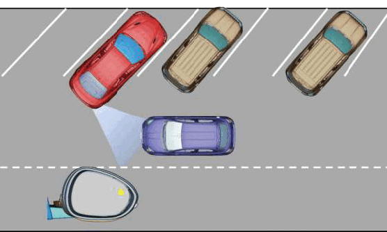
REAR CROSS PATH DETECTION:
The system monitors the vehicles or objects in the rear area of the vehicle (always through the two radars which also perform the BSM function) having a perpendicular movement to the vehicle and speed lower than 35 km/h (22 mph), during reversing maneuvers providing feedback to the driver via buzzer and/or visual icons.
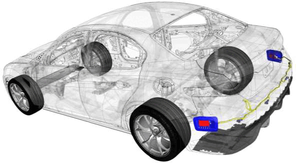
LEFT AND RIGHT BLIND SPOT SENSORS (LBSS/RBSS)
The radar sensors have an operation frequency that ranges from about 24 GHz to 200 MHz Pin.
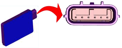
LBSS
| TERMINAL | FUNCTION |
|---|---|
| 1 | 12V POWER |
| 2 | LED SIGNAL |
| 3 | CAN HIGH |
| 4 | N/A |
| 5 | CAN LOW |
| 6 | GROUND |
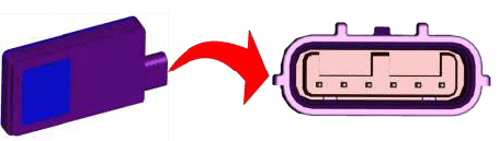
RBSS
| TERMINAL | FUNCTION |
|---|---|
| 1 | 12V POWER |
| 2 | LED SIGNAL |
| 3 | CAN HIGH |
| 4 | GROUND |
| 5 | CAN LOW |
| 6 | GROUND |
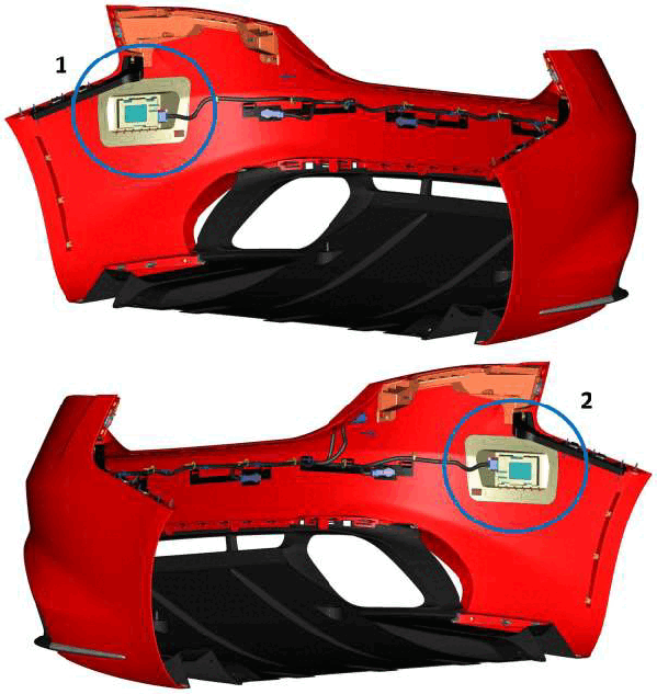
Two sensors are positioned on the inner side near the rear fascia.
- RBSS (1)
- LBSS (2)
OPERATION
The primary components of the BSM system are the Electronic Control Units (ECU) integral to each of the two RADAR sensors, one behind each outboard side of the rear bumper fascia. Each ECU operates on battery current received from a fuse in the Body Control Module (BCM) whenever the status of the ignition is ON and the ECU has a path to ground at all times through a take out and eyelet terminal of the body wire harness that is secured to the body sheet metal. Each of these ECU communicate with each other as well as with other electronic modules in the vehicle over the Controller Area Network (CAN) data bus network.
The BSM system ECU continually monitor all of the BSM system circuits and components for readiness, and will store a Diagnostic Trouble Code (DTC) for any fault that is detected. The ECU also communicate with a diagnostic scan tool over the CAN data bus. When a BSM system ECU stores a DTC, it sends an electronic request message to the Instrument Panel Cluster (IPC) and a SERVICE BLIND SPOT SYSTEM or BLIND SPOT SYSTEM TEMPORARILY UNAVAILABLE textual message is displayed by the IPC to alert the vehicle operator.
The BSM system ECU receive and analyze data inputs directly from the radar sensors, calculate and provide the proper hard wired outputs to illuminate the visual alert displays in their respective right or left outside rear view mirrors, as well as calculate and communicate the proper audible alert output requests to the IPC over the CAN data bus.
The BSM radar sensors allow the BSM system ECU to locate and identify nearby objects of interest meeting the criteria established by algorithms within the system software. The BSM displays provide the vehicle operator with a visual alert indicating that an object of interest has been detected within one of the vehicle detection zones. The BSM audible alerts are then issued by the IPC based upon electronic audible alert request messages received from the BSM system ECU. The BSM system ECU also send electronic radio mute request messages over the CAN data bus to the Radio/Entertainment Telematics Module (ETM) whenever an audible alert is requested. This message activates the radio mute function while the audible alert is being sounded, then resumes normal radio function when the alert is completed.