Theory Of Operation
Engine Stop/Start (ESS) Operation: The ESS system uses two separate Starter Relays to control engine cranking. One relay is controlled by the Body Control Module (BCM). The other relay is controlled by the Powertrain Control Module (PCM). During a key start event, the BCM controlled Starter Relay 2 is commanded closed by the BCM. The Fused B+ output from the relay supplies voltage to the Fused B+ terminal (pin 30) of the PCM controlled Starter Relay. The PCM simultaneously commands Starter Relay 1 closed which allows the Fused B+ voltage to pass on to the Starter Solenoid. After the relay diagnostics have passed, the BCM controlled Starter Relay 2 is commanded on (closed), and the PCM controlled Starter Relay 1 is commanded off (open). During a Stop/Start event, The PCM controls cranking by open and closing Starter Relay 1.
Engine Stop/Start (ESS) Diagnostics: The PCM performs diagnostics on the Starter Relay control circuitry and the Starter Relay Output circuitry, as well diagnostics for a stuck closed Starter Relay.
- The PCM performs circuit fault detection diagnostics on the Starter Relay 1 High Side Driver (HSD) Control circuit. The BCM will send a CAN Bus message to the PCM if there is a fault in the Starter Relay 2 Control circuitry.
- After the engine is started with a key start, the PCM performs a diagnostic on the relays to determine is either relay is stuck in the closed position. To do this the Powertrain Control Module (PCM) will monitor for voltage on the Starter Relay Output circuit, command one of the Starter Relays closed and the other Starter Relay open. It will then open the closed relay, and close the open relay. If there is voltage present on the Starter Relay Output circuit during either of these conditions, then the relay that was commanded off when voltage was detected is determined to be stuck closed. The PCM also monitors for voltage on the Starter Relay Output circuit for fault detection in the Starter Relay Output circuit.
- The PCM will monitor for voltage on the Starter Relay Output circuit at all times (during engine crank request on or off) for fault detection in the Starter Relay Output circuit.
If the ESS system fails any of the Starter Relay or Starter Relay Output circuit diagnostics, the ESS system will be disabled during that drive cycle.
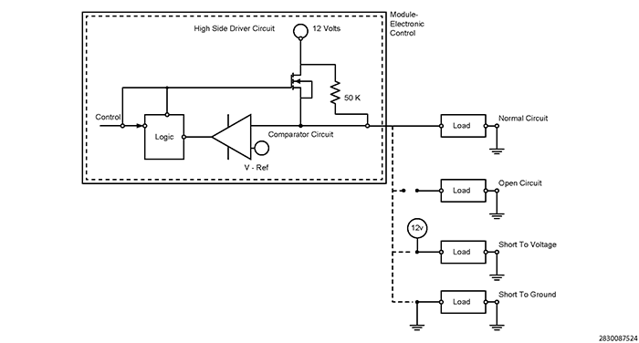
Typical High Side Driver Operation and Fault Detection: This type of driver circuit is generally used for relay control, solenoid control or a similar type of driver device. The PCM provides 12 volts to operate the device when switched on. The voltage could be constant or Pulse Width Modulated (PWM). The PCM also provides fault detection for the device, wiring and internal driver. Fault detection can be done by monitoring voltage on the circuit, current draw, or a combination of both. The graphic shows how the PCM performs diagnostics using an internal pull up diagnostic resistor and calibrated voltage reference (V-Ref) as a comparator for fault detection.
- Circuit Open and Circuit High Detection: The PCM monitors for an open circuit and short to voltage when the internal driver is switched off. A milliampere voltage is provided to the device through the internal pull up diagnostic resistor connected in series with the device. The diagnostic voltage is monitored between the pull up resistor and device, and compared to V-Ref. If the resistance in the device or circuitry becomes too large (approaches open) the voltage supply will increase on the comparator circuit and become greater than V-Ref, and a fault is detected. A short to Battery voltage will have the same effect. An alternative method of fault detection for an open that is used is to monitor current draw when the internal driver is switched on. If the module does not detect any current draw it determines that the component or circuitry is open.
- Circuit Low Detection: The PCM monitors for a short to ground when the driver is turned on. When switched on, the voltage to the device should be close to the 12 volt supply voltage. A short to ground will pull the voltage at the comparator circuit below V-Ref and a circuit low fault is detected. An alternative method of fault detection for a short to ground that is used is to monitor current draw when the internal driver is switched on. Excessive current draw detected would indicate a short to ground.