Theory Of Operation
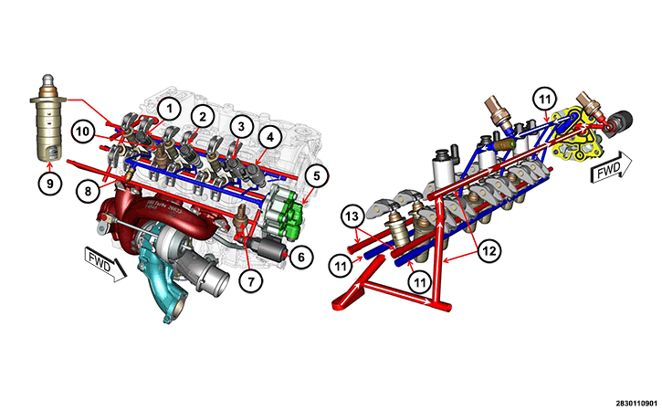
When all conditions have been met for Multiple Displacement Solenoid (MDS) operation, each MDS is energized by the Powertrain Control Module (PCM) to transition the engine from 6 cylinder mode to 3 cylinder mode. By energizing the solenoid, oil pressure is supplied through a passageway in the Cylinder Head to the pair of lifters that coincide with each particular solenoid. The oil pressure pushes in the locking pins that allows the lifter to collapse, decoupling the valves and camshaft. It takes approximately 21.75 psi (1.5 bar) for the solenoids to operate properly. In order to maintain the oil pressure above the necessary amount, there is a boost oil pump that raises the supply oil to between approximately 43.5-50.74 psi (3-3.5 bar). The system has a mechanical pressure relief valve which will open above 87 psi (6 bar), preventing the pressure from increasing too high. There is an oil pressure sensor in the passageway to the solenoids that is used to monitor for proper oil pressure in the system. See the figure below to help identify the MDS components.
| NUMBER | COMPONENT | FUNCTION |
|---|---|---|
| 1 | Multiple Displacement Solenoid (MDS) 1 | Controls oil flow to the Intake Lifters for MDS operation on cylinders #2 and #3 |
| 2 | Multiple Displacement Solenoid (MDS) 2 | Controls oil flow to the Exhaust Lifters for MDS operation on cylinders #2 and #3 |
| 3 | Multiple Displacement Solenoid (MDS) 3 | Controls oil flow to the Exhaust Lifter for MDS operation on cylinder #1 |
| 4 | Multiple Displacement Solenoid (MDS) 4 | Controls oil flow to the Intake Lifter for MDS operation on cylinders #1 |
| 5 | Cylinder Deactivation Boost Pump | Increases the oil pressure for the MDS System operation |
| 6 | Turbocharger Oil Deactivation Solenoid | Controls flow of the lubrication oil to the Turbocharger |
| 7 | Oil Pressure Sensor 2 | Used to monitor oil pressure in the Turbocharger Oil Deactivation circuit |
| 8 | Oil Pressure Relief Valve | Regulates oil pressure for MDS System |
| 9 | Collapsible Lifters | Disengage the Valves during MDS mode |
| 10 | Oil Pressure Sensor 3 | Used to monitor oil pressure in the MDS circuit |
| 11 | MDS Oil delivery circuit | Oil supply to the Collapsible Lifters from the Boost Pump for MDS Operation |
| 12 | Oil input to Boost Pump | Oil supply to the Boost Pump for MDS operation |
| 13 | Oil lubrication circuit for Lifters | Normal oil flow to the Lifters |
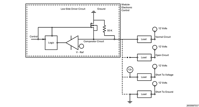
Typical Low Side Driver Operation and Fault Detection: This type of driver circuit is generally used for relay control, controlling a solenoid or a similar type of driver device. The PCM provides a ground to operate the device when switched on. The PCM also provides fault detection for the device, wiring and internal driver. For diagnostic purposes the PCM uses an internal pull down diagnostic resistor connected in series and a voltage reference (V-Ref) comparator for fault detection:
- Circuit Open and Circuit Low Detection: The PCM monitors for an open circuit and short to ground when the driver is switched off. When switched off, the available voltage passes through the device and the internal pull down resistor connected in series. The voltage at the comparator circuit should be close to Battery voltage since the majority of the voltage drop occurs through the diagnostic resistor. If the available voltage is less than the V-Ref, a fault is set. In this case the V-Ref would be slightly below Battery voltage.
- Circuit High Detection: The PCM monitors for a short to voltage when the driver is switched on. When the driver is switched on providing a path to ground through the transistor, the available voltage should be pulled low near zero volts since the comparator circuit is monitoring the ground side of the device. If the voltage is greater than the V-Ref, a fault is detected. In this case V-Ref would be slightly above zero volts.
A load that has a resistance that is below manufacturer specification, or a second load device shorted to the low side driver circuit can cause excessive current draw on the internal driver. The driver will be switched off to protect against overheating and damaging the driver. In this instance the Circuit High fault may be detected because the available voltage on the comparator circuit is above V-Ref.