Theory Of Operation
WARNING: This page is about a different variant/trim than selected.
When all conditions have been met for Multiple Displacement Solenoid (MDS) operation, each MDS is energized by the Powertrain Control Module (PCM) to transition the engine from 6 cylinder mode to 3 cylinder mode. By energizing the solenoid, oil pressure is supplied through a passageway in the engine to the pair of lifters that coincide with each particular solenoid. The oil pressure pushes in the locking pins that allows the lifter to collapse, decoupling the valves and Camshaft. The PCM performs fault detection diagnostics to determine if the solenoid is operating properly both when the solenoid is energized (deactivating the cylinder) and de-energized (reactivating the cylinder).
- During Deactivation the monitor checks the MDS cylinders for both air and fuel to be turned off when MDS is turned on. If firing events are detected for a cylinder, this would indicate that the cylinder is still operating and a fail counter will increment. Once the fail counter reaches a calibrated threshold, a fault will set and MDS operation is disabled for the remainder of the trip.
- During Reactivation the monitor checks that the MDS cylinders have powered up when MDS is turned off. Misfire detection is used to diagnose whether the cylinder has powered back up after being deactivated. When MDS is off, no misfire events should be detected on any of the MDS cylinders. When a calibrated number of misfire events are detected a fail counter will increment. Once this fail counter reaches a calibrated threshold a fault will set.
- There is a performance check that is performed by the PCM after a deactivation has occurred. The PCM monitors the O2 Sensor and fuel trim for the entire bank and compares the difference in fuel trim between 6 cylinder mode and 3 cylinder mode. If the difference is not large enough after switching, a fault will set.
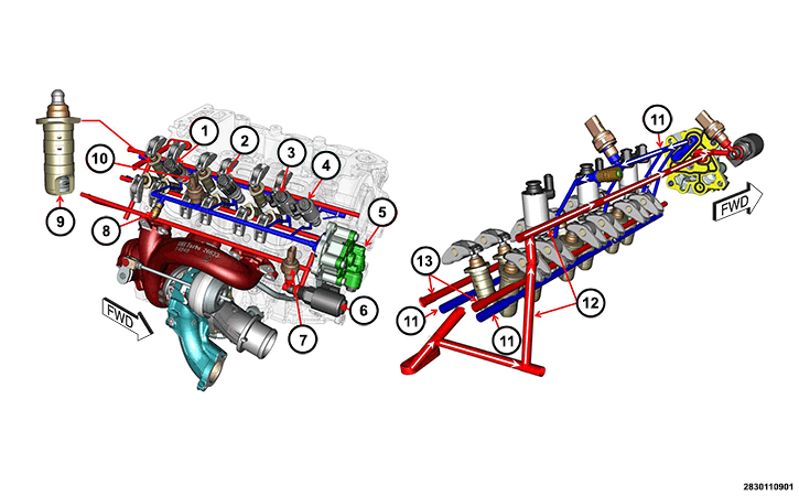
| NUMBER | COMPONENT | FUNCTION |
|---|---|---|
| 1 | Multiple Displacement Solenoid (MDS) 1 | Controls oil flow to the Intake Lifters for MDS operation on cylinders #2 and #3 |
| 2 | Multiple Displacement Solenoid (MDS) 2 | Controls oil flow to the Exhaust Lifters for MDS operation on cylinders #2 and #3 |
| 3 | Multiple Displacement Solenoid (MDS) 3 | Controls oil flow to the Exhaust Lifter for MDS operation on cylinder #1 |
| 4 | Multiple Displacement Solenoid (MDS) 4 | Controls oil flow to the Intake Lifter for MDS operation on cylinders #1 |
| 5 | Cylinder Deactivation Boost Pump | Increases the oil pressure for the MDS System operation |
| 6 | Turbocharger Oil Deactivation Solenoid | Controls flow of the lubrication oil to the Turbocharger |
| 7 | Oil Pressure Sensor 2 | Used to monitor oil pressure in the Turbocharger Oil Deactivation circuit |
| 8 | Oil Pressure Relief Valve | Regulates oil pressure for MDS System |
| 9 | Collapsible Lifters | Disengage the Valves during MDS mode |
| 10 | Oil Pressure Sensor 3 | Used to monitor oil pressure in the MDS circuit |
| 11 | MDS Oil delivery circuit | Oil supply to the Collapsible Lifters from the Boost Pump for MDS Operation |
| 12 | Oil input to Boost Pump | Oil supply to the Boost Pump for MDS operation |
| 13 | Oil lubrication circuit for Lifters | Normal oil flow to the Lifters |