Theory Of Operation
The base Turbocharger boost pressure is managed by the mechanical Wastegate. The Wastegate is a spring loaded mechanical valve that is normally open, allowing the exhaust gases to bypass the turbine inside the Turbocharger. When the Powertrain Control Module (PCM) decides to allow boost, it energizes the Wastegate Solenoid, allowing vacuum to be applied to a diaphragm that works against the spring pressure of the Wastegate. The vacuum is low at lower engine speeds and increases as engine speed increases. The increase in vacuum with engine speed controls the rate that the Wastegate opens. As the vacuum increases and closes the Wastegate, it allows more of the exhaust gases to be directed through the turbine, increasing the turbine speed and amount of boost by the Turbocharger.
The PCM controls the Wastegate Solenoid through a Low Side Driver (LSD) circuit. The Wastegate Solenoid is located between the Engine Vacuum Pump and mechanical Wastegate. When energized by the PCM, the Wastegate Solenoid allows supply vacuum from the pump to act on the diaphragm connected to the Wastegate. The PCM monitors the signal from the Wastegate internal position sensor to determine when the Wastegate has reached the position.
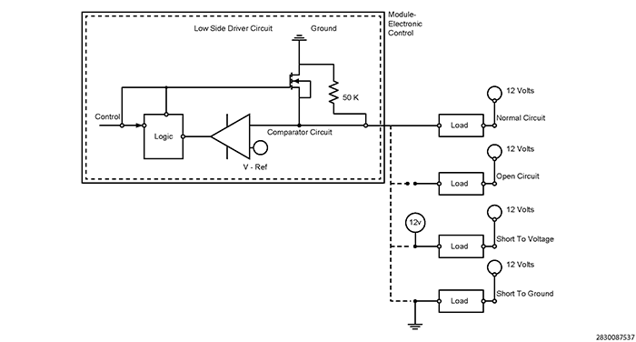
Typical Low Side Driver Operation and Fault Detection: This type of driver circuit is generally used for relay control, solenoid control or a similar type of driver device. The PCM provides a ground to operate the device when switched on. The ground could be constant or Pulse Width Modulated (PWM). The PCM also provides fault detection for the device, wiring and internal driver. Fault detection can be done by monitoring voltage on the circuit, current draw, or a combination of both. For diagnostic purposes the PCM uses an internal pull down diagnostic resistor connected in series and a voltage reference (V-Ref) comparator for fault detection:
- Circuit Open and Circuit Low Detection: The PCM monitors for an open circuit and short to ground when the driver is switched off. When switched off, the available voltage passes through the device and the internal pull down resistor connected in series. The voltage at the comparator circuit should be close to Battery voltage since the majority of the voltage drop occurs through the diagnostic resistor. If the available voltage is less than the V-Ref, a fault is set. In this scenario the V-Ref would be slightly below Battery voltage. An alternative method of fault detection for an open or short to ground that is used is to monitor current draw when the internal driver is switched on. If the module does not detect any current draw it determines that the component or circuitry is open. Excessive current draw detected would indicate a short to ground.
- Circuit High Detection: The PCM monitors for a short to voltage when the driver is switched on. When the driver is switched on providing a path to ground through the transistor, the available voltage should be pulled low, near zero volts since the comparator circuit is monitoring the ground side of the device. If the voltage is greater than V-Ref, a fault is detected. In this scenario V-Ref would be slightly above zero volts.
A load that has a resistance that is below manufacturer specification, or a second load device shorted to the low side driver circuit can cause excessive current draw on the internal driver. The driver will be switched off to protect against overheating and damaging the driver. In this instance the Circuit High fault may be detected because the available voltage on the comparator circuit is above V-Ref.