Theory Of Operation
General Operation: The Direct Injection system sprays fuel at a very high pressure directly into the combustion chamber. There are two sides to the fuel system, the low pressure (supply) side and high pressure (control) side. The high pressure is created by the High Pressure Fuel Pump assembly (described below). The Powertrain Control Module (PCM) monitors the fuel pressure on both sides of the system.
- Low Pressure (supply) Side: The low pressure side of the system uses an electric Fuel Pump Module in the Fuel Tank to supply fuel to the High Pressure Fuel Pump at approximately 58.0 psi. The PCM receives feedback from the Fuel Pressure Sensor to monitor the pressure on low pressure side of the system.
- High Pressure (control) Side: The fuel pressure is increased by the High Pressure Fuel Pump which has a plunger that is mechanically driven by four lobes on the Camshaft. The fuel pressure on the high side of the system is controlled by a Fuel Quantity Solenoid (FQS) integrated on the pump which controls the flow of fuel into the chamber. The high fuel pressure to the Common Fuel Rail and Fuel Injectors is regulated by the PCM. The PCM receives feedback from the Fuel Rail Pressure (FRP) Sensor to control and monitor the pressure on high pressure side of the system.
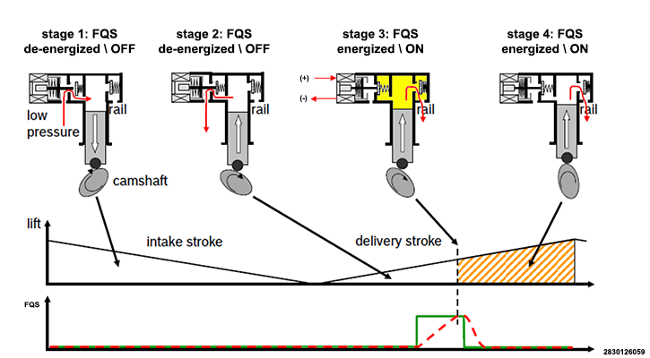
High Pressure Fuel Pump Operation: To control the pressure, the PCM uses a rail mounted Fuel Rail Pressure (FRP) Sensor and a normally open inlet valve integral to the engine mounted High Pressure Fuel Pump. The inlet valve is closed by the Fuel Quantity Solenoid. The PCM controls the Fuel Quantity Solenoid with a Pulse Width Modulated (PWM) signal synchronized to the Camshaft position. The High Pressure Fuel Pump operates as a spill valve, allowing the pump to spill fuel back through the inlet valve as the plunger moves down and up until the valve is closed. When the PCM determines that the remaining portion of the plunger upstroke would result in the correct fuel volume required to maintain rail pressure, the inlet valve is closed by the FQS and the fuel is pressurized past the outlet check valve and into the Fuel Rail. The figure below depicts the flow of fuel through the High Pressure Fuel Pump.
Diagnostics: The PCM performs diagnostics on the Fuel Quantity Solenoid, Fuel Pressure Sensor, Fuel Rail Pressure (FRP) Sensor and related wiring for opens or shorts. An open or short in solenoid or either of the sensors or related wiring will result in a correlating circuit fault. The FRP Sensor has a shared 5-Volt Supply and Sensor Ground. There are two internal pressure sensors that provide signals to the PCM. The PCM performs circuit diagnostics on each signal as well as a rationality check between the signals. The PCM also compares the desired fuel rail pressure to the actual fuel rail pressure. If the difference is more than a calibrated threshold, a fuel rail system pressure performance fault is set.