Engine Removal And Installation - AWD
REMOVAL
- Raise and support the vehicle. Refer to HOISTING, STANDARD PROCEDURE .
- Disconnect and isolate the negative battery cable.
- Remove the front fascia. Refer to FASCIA, FRONT, REMOVAL AND INSTALLATION .
- Remove the air dam front crossmember. Refer to AIR DAM, FRONT, REMOVAL AND INSTALLATIONAIR DAM, FRONT CROSSMEMBER, REMOVAL AND INSTALLATION .
- Drain the engine cooling system. Refer to DRAINING AND FILLING THE ENGINE COOLING SYSTEM .
- Drain the turbocharger cooling system. Refer to DRAINING AND FILLING THE TURBOCHARGER COOLING SYSTEM .
- Recover the A/C refrigerant. Refer to PLUMBING, STANDARD PROCEDURE .
- Remove the Powertrain control Module (PCM) and bracket assembly. Refer to MODULE, POWERTRAIN CONTROL (PCM), REMOVAL AND INSTALLATION .
- Remove the cowl panel cover. Refer to COVER, COWL PANEL, REMOVAL AND INSTALLATION .
- Remove the turbocharger intake air tube. Refer to TUBE, INTAKE AIR, REMOVAL AND INSTALLATION .
- Remove the air cleaner body. Refer to BODY, AIR CLEANER, REMOVAL AND INSTALLATION .
- Remove the exhaust pipe. Refer to PIPE, EXHAUST, REMOVAL AND INSTALLATION .
- Remove the rear propeller shaft. Refer to REMOVAL AND INSTALLATION .
- Remove the front struts. Refer to STRUT, SUSPENSION, ASSEMBLY, REMOVAL AND INSTALLATION .
- Remove both front half shafts. Refer to REMOVAL AND INSTALLATIONREMOVAL AND INSTALLATION
.
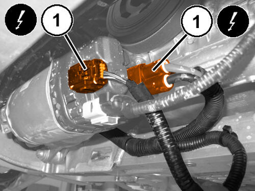
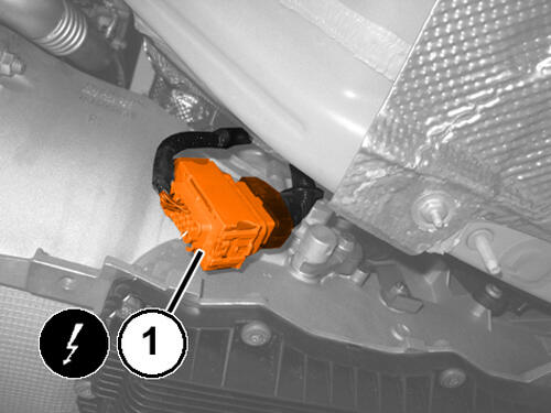
- Disconnect the steering gear wire harness connectors (1).
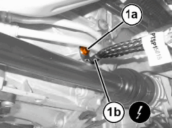
- Remove and DISCARD
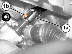
the bolt (1a) and disconnect the column (1b) from the steering gear.
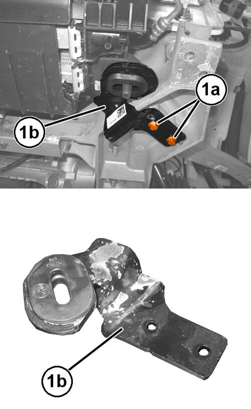
- On both sides, remove the bolts (1a) and the radiator mounting brackets (1b).
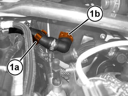
- Open the clip (1a) and disconnect the quick coupling (1b) from the heater core engine coolant return hose.
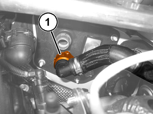
- Disconnect the quick coupling and remove the engine coolant supply hose (1) from the heater core.
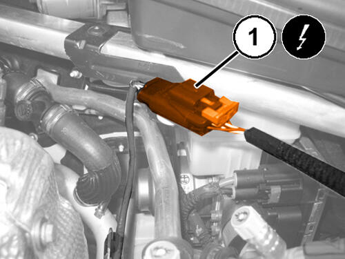
- Disengage and disconnect the downstream oxygen sensor wire harness connector (1).
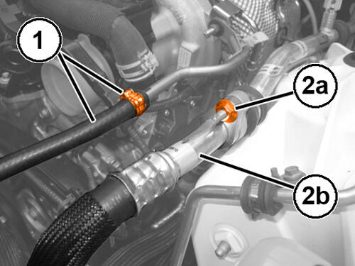
- Loosen the clamp (1) and disconnect the engine coolant outlet hose from the turbocharger.
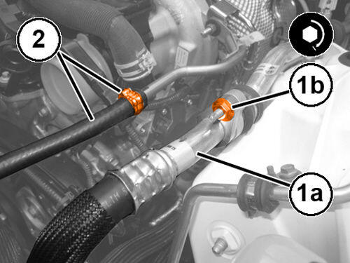
- Remove the nut (2a) and disconnect the air conditioning lines (2b).
- Using suitable seal plugs close the disconnected unions to prevent moisture and impurities from entering the A/C system.
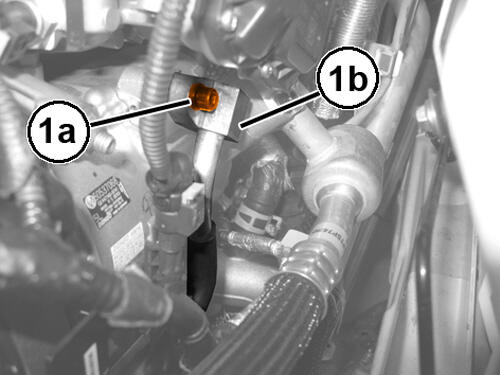
- Remove the bolt (1a) and disconnect the outlet piping from the A/C compressor (1b).
- Using suitable seal plugs close the disconnected unions to prevent moisture and impurities from entering the system.
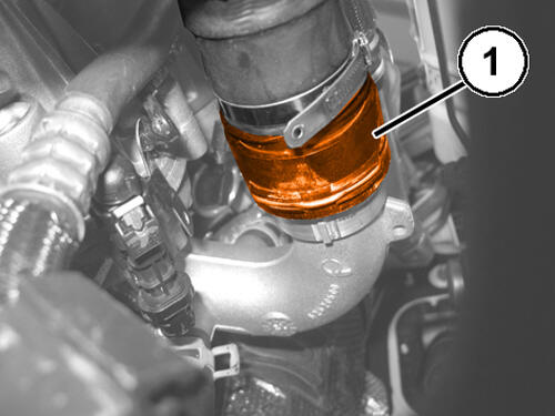
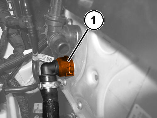
- Disconnect the quick coupling and remove the engine coolant hose (1) from the temperature control solenoid valve.
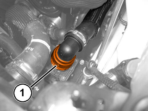
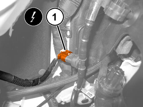
- Disconnect the quick coupling (1) and remove the engine coolant inlet hose from the water pump.
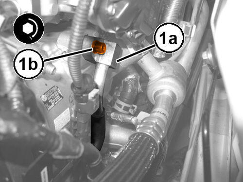
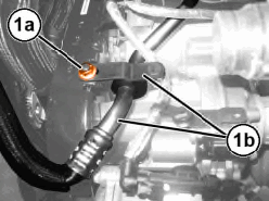
- Remove the retaining nut (1a) from the compressor to condenser A/C line (1b).
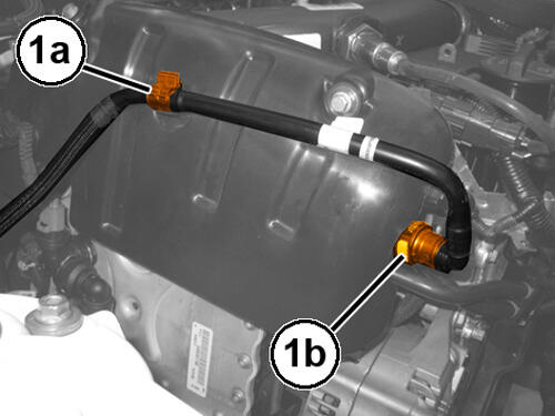
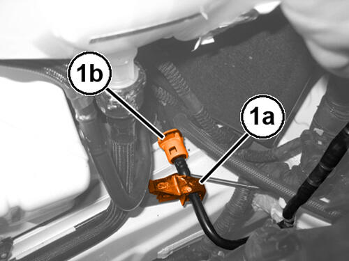
- Open the clip (1a) and disconnect the fuel vapor tube quick coupling (1b).
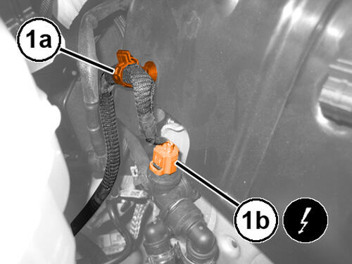
- Open the clip (1a) and disconnect the coolant temperature sensor wire harness connector (1b).
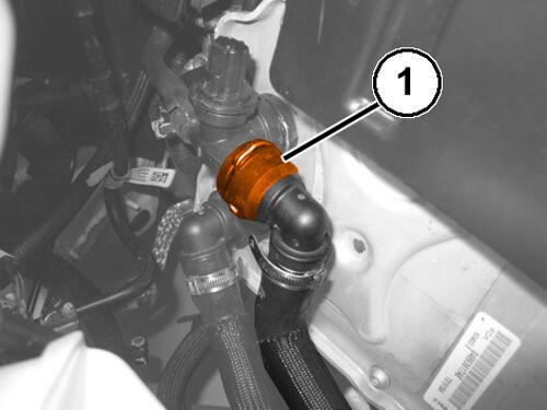
- Disconnect the quick coupling and remove the engine coolant delivery hose (1) from the heat exchanger.
- Disconnect the quick coupling and remove the engine coolant return hose (1) from the heat exchanger.
- Disconnect the fuel low pressure sensor wire harness connector (1).
- Open the clip (1a) and disconnect the quick coupling (1b) of the front fuel supply pipe from the pressure pump.
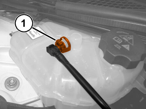
- Disconnect the degassing hose quick coupling (1) from the pressurized coolant bottle.
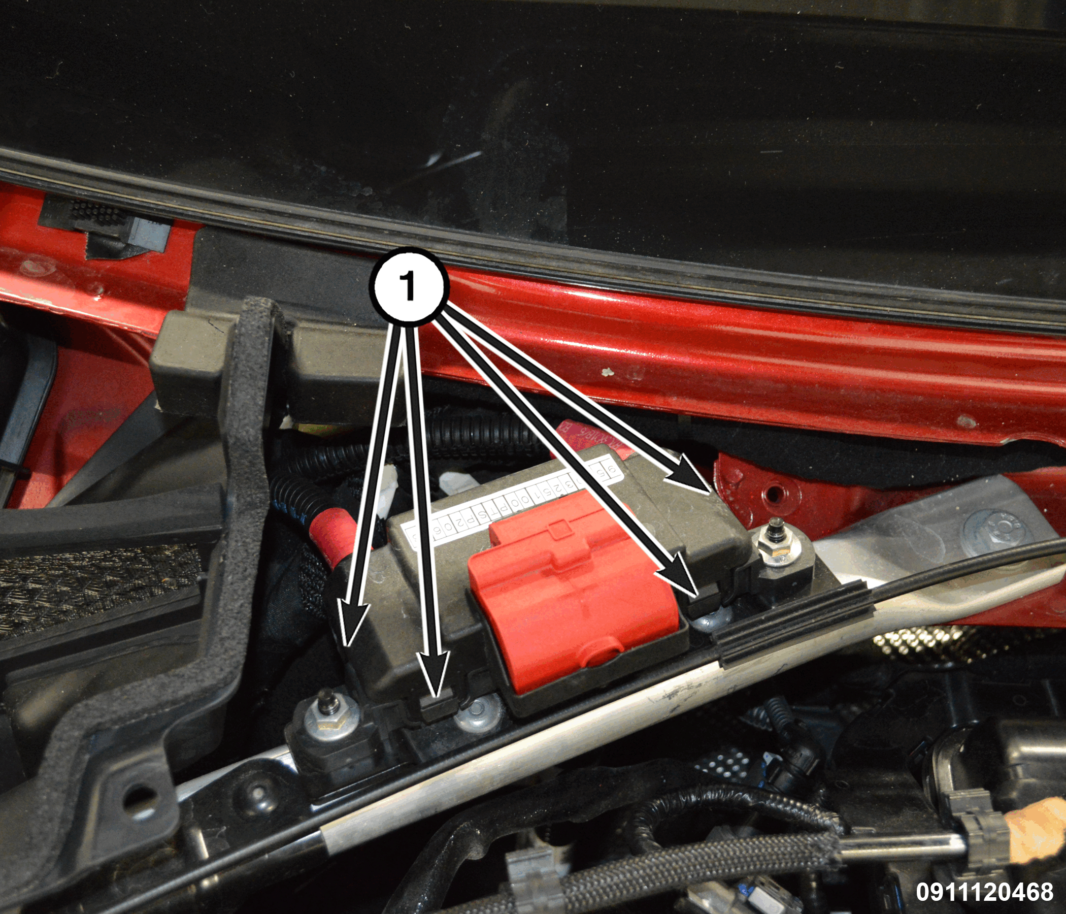
- With cowl panel cover removed, remove the start cable junction cover by releasing the four tabs (1).
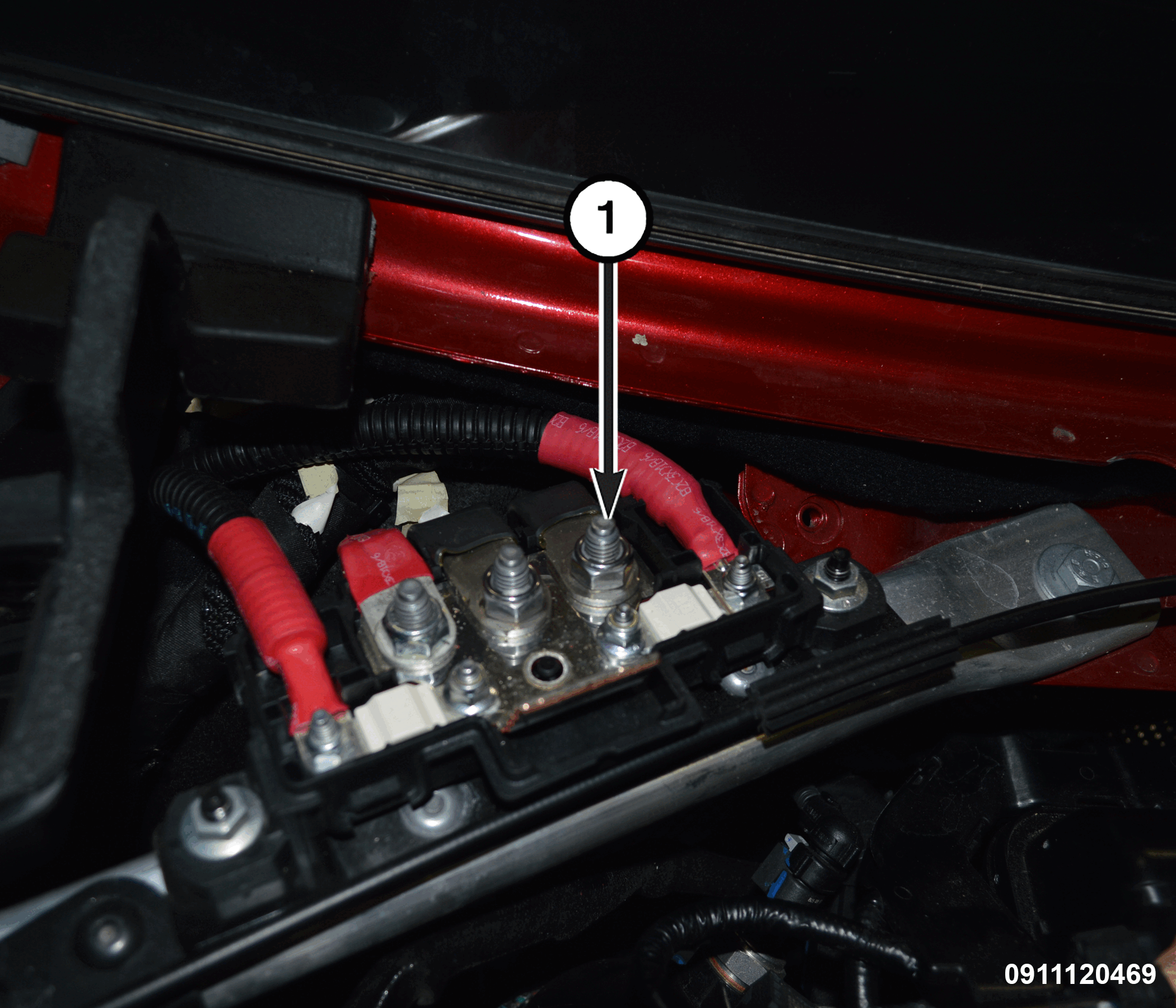
- Disconnect the starter motor B+ cable (1) from the junction.
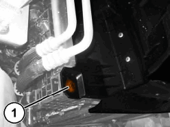
- On both sides, remove the lower bolts (1) securing the air duct to the radiator.
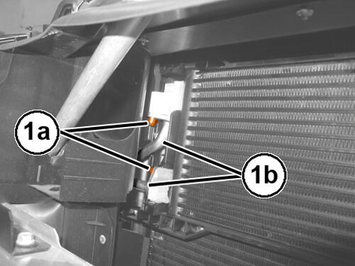
- Remove the bolts (1a), disconnect and reposition the automatic transmission oil delivery and return lines from the radiator (1b).
- Remove the bolt (1a) and disconnect the ground lead (1b).
- Disengage and disconnect the automatic transmission wiring harness connector (1).
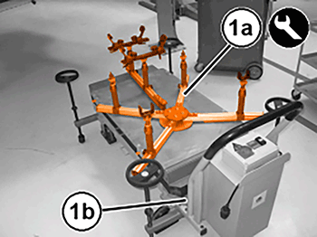
- Place Engine Support 2032200090 (1a) on a suitable lifting table (1b).
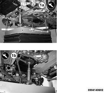
- Position the Engine Support 2032200090 under the powertrain and support the suspension cross member with the uprights (1a) and the transmission with the uprights (1b).
- If the Engine Support 2032200090 is not available, place commercially available rubber spacer blocks, such as ROTFJ2427/J2440 or equivalent, on the (special tool #BX50-CHR, Table, Bishamon Lift) and position it under the powertrain and suspension crossmember assembly.
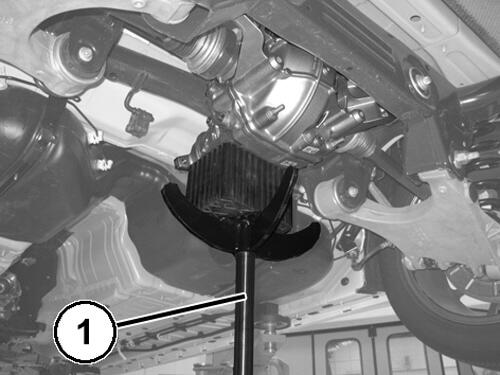
- Position a suitable hydraulic lift (1) under the rear differential and support it as shown in the illustration.
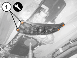
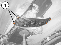
- Remove the transmission mounting bracket bolts (1).
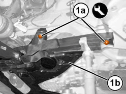
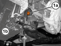
- On both sides, remove the front screws (1a) securing the front suspension cross member (1b) to the body.
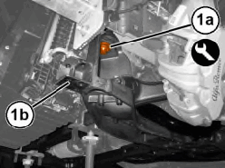
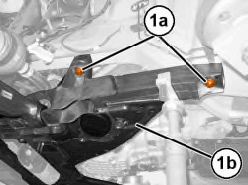
- On both sides, remove the middle and rear bolts (1a) securing the front suspension cross member (1b) to the body.
- Lower the lift table away from the vehicle complete with the powertrain assembly and suspension crossmember.
INSTALLATION
- Use Engine Support 2032200090 on a suitable lifting table to install the powertrain assembly and suspension crossmember in position.
- If the Engine Support 2032200090 is not available, use the (special tool #BX50-CHR, Table, Bishamon Lift) and commercially available rubber spacer blocks such as ROTFJ2427/J2440 or equivalent to install the powertrain assembly and suspension crossmember in position.
- On both sides, Install the NEW
middle bolts (1a) and rear bolts (1b) securing the front suspension cross member to the body and tighten to the proper specification Refer to TECHNICAL SPECIFICATIONS
.
- On both sides, Install the NEW
front bolts (1a) securing the front suspension cross member (1b) to the body and tighten to the proper specification Refer to TECHNICAL SPECIFICATIONS
.
- Install the NEW rear engine/transmission mount lower bracket bolts and tighten to the proper specification Refer to TORQUE SPECIFICATIONS .
- Remove the lift table complete with rubber spacer blocks such as ROTFJ2427/J2440 or equivalent supporting the powertrain assembly.
- Connect the automatic transmission wiring harness connector.
- Connect the ground lead and securely tighten the bolt.
- Install the automatic transmission oil delivery and return lines from the radiator and securely tighten the bolts.
- Install the front bolts securing the air duct to the radiator and securely tighten.
- Connect the starter motor B+ wiring harness, securely tighten the nut and install the protective cover.
- Connect the degassing hose quick coupling to the pressurized coolant bottle.
- Connect the quick coupling of the front fuel supply line to the pressure pump and close the retaining clip.
- Connect the fuel low pressure sensor wiring harness connector.
- Connect the quick coupling of the engine coolant return hose to the heat exchanger.
- Connect the quick coupling of the engine coolant supply hose to the heat exchanger.
- Connect the coolant temperature sensor wiring harness connector and close the retaining clip.
- Connect the fuel vapor line quick coupling and close the retaining clip.
- Connect the quick coupling of the engine coolant inlet hose to the water pump.
- Connect the quick coupling of the engine coolant hose to the coolant temperature control valve.
- Remove the protective plugs from the opened refrigerant line fittings and ports.NOTE:
Lubricate NEW rubber O-ring seals with clean refrigerant oil and install them and new gaskets onto the discharge line fittings. Use only the specified O-rings as they are made of a special material for the system. Use only refrigerant oil of the type recommended for the A/C compressor in the vehicle.
- Install the refrigerant line (1a) to the A/C compressor and tighten the bolt (1b) to the proper specification Refer to TECHNICAL SPECIFICATIONS
.
- Remove the protective plugs from the opened refrigerant line fittings and ports.NOTE:
Lubricate NEW rubber O-ring seals with clean refrigerant oil and install them and new gaskets onto the discharge line fittings. Use only the specified O-rings as they are made of a special material for the system. Use only refrigerant oil of the type recommended for the A/C compressor in the vehicle.
- Connect the A/C lines (1a) and tighten the nut (1b) to the proper specification Refer to TECHNICAL SPECIFICATIONS .
- Connect the downstream oxygen sensor wiring harness connector and engage it in the support bracket.
- Connect the engine coolant supply hose quick coupling to the heater core.
- Connect the engine coolant return hose quick coupling to the heater core.
- On both sides, Install the radiator mounting brackets and securely tighten the bolts.
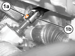
- Connect the column (1a) to the steering gear and tighten the NEW bolt (1b) to the proper specification Refer to TECHNICAL SPECIFICATIONS .
- Connect the steering gear wiring harness connector.
- Install both front half shafts. Refer to REMOVAL AND INSTALLATION .
- Install the front struts. Refer to STRUT, SUSPENSION, ASSEMBLY, REMOVAL AND INSTALLATION .
- Install the propeller shaft. Refer to REMOVAL AND INSTALLATION .
- Install the exhaust pipe. Refer to PIPE, EXHAUST, REMOVAL AND INSTALLATION .
- Install the air cleaner body. Refer to BODY, AIR CLEANER, REMOVAL AND INSTALLATION .
- Install the intake air tube. Refer to TUBE, INTAKE AIR, REMOVAL AND INSTALLATION .
- Install the cowl panel cover. Refer to COVER, COWL PANEL, REMOVAL AND INSTALLATION .
- Install the Powertrain control Module (PCM) and bracket assembly. Refer to MODULE, POWERTRAIN CONTROL (PCM), REMOVAL AND INSTALLATION .
- Evacuate and charge A/C system. Refer to PLUMBING, STANDARD PROCEDURE .
- Fill the turbocharger cooling system. Refer to DRAINING AND FILLING THE TURBOCHARGER COOLING SYSTEM .
- Fill the cooling system. Refer to DRAINING AND FILLING THE ENGINE COOLING SYSTEM .
- Install the air dam front crossmember. Refer to AIR DAM, FRONT, REMOVAL AND INSTALLATIONAIR DAM, FRONT CROSSMEMBER, REMOVAL AND INSTALLATION .
- Install the front fascia. Refer to FASCIA, FRONT, REMOVAL AND INSTALLATION .
- Connect the negative battery cable.
- If removed, install the oil filter and fill the engine crankcase with the proper oil to the correct level. Refer to CAPACITIES AND RECOMMENDED FLUIDS, SPECIFICATIONS .
- Remove the support and lower the vehicle.
- Perform a wheel alignment. Refer to WHEEL ALIGNMENT, STANDARD PROCEDURE .