Engine And Transmission Separation From CROSSMEMBER RWD
REMOVAL
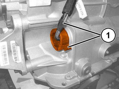
- Turn the ring nut (1) counterclockwise to disconnect the solenoid valve assembly connector.
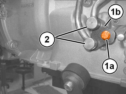
- Remove the bolt (1a) and the plate (1b).
- Disconnect the transmission fluid supply and return pipe connectors (2).
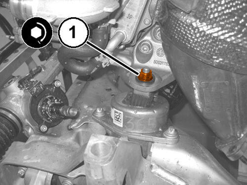
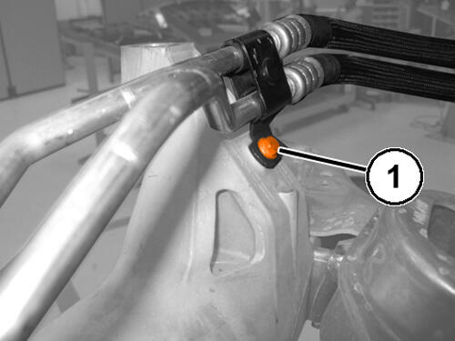
- Remove the bolt (1) securing the transmission fluid lines to the front suspension crossmember.
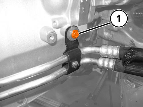
- Remove the bolt (1) securing the transmission fluid lines to the transmission bell housing.
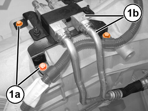
- Remove the bolts (1a) securing the thermostat valve support bracket (1b).
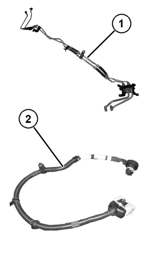
- Remove the transmission fluid lines (1) complete with O-rings.
- Remove the automatic transmission wiring harness (2).
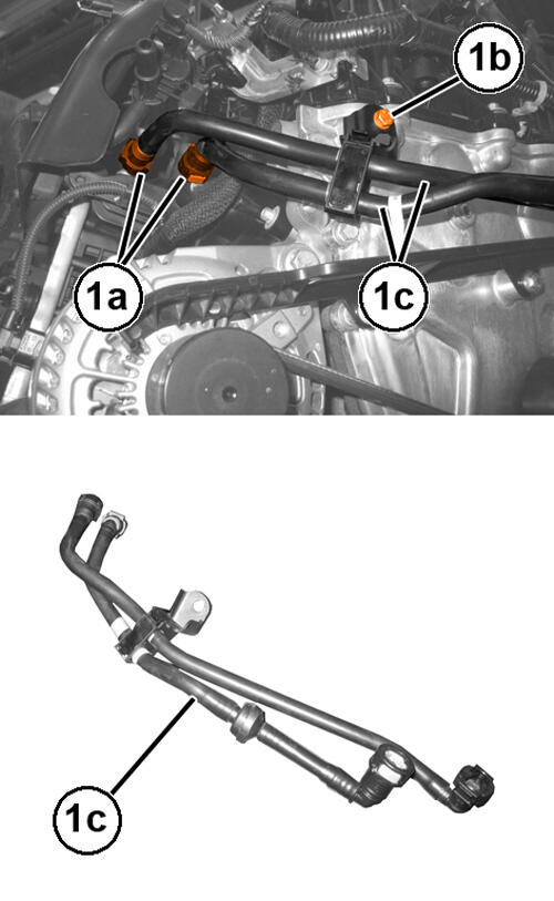
- Disconnect the quick connectors (1a), remove the bolt (1b) and the vacuum and fuel vapor lines (1c).
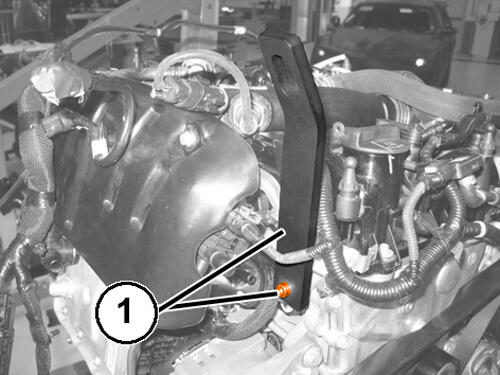
- Install a suitable bracket (1) for lifting the powertrain assembly as shown in the illustration and securely tighten the bolt.
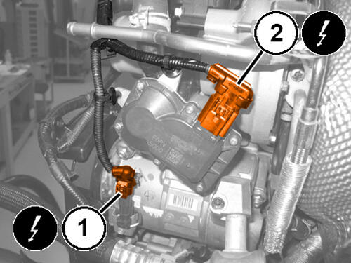
- Disconnect the A/C compressor wire harness connector (1).
- Disconnect the low pressure EGR solenoid valve wire harness connector (2).
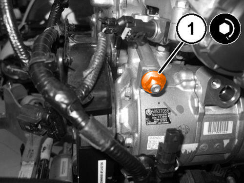
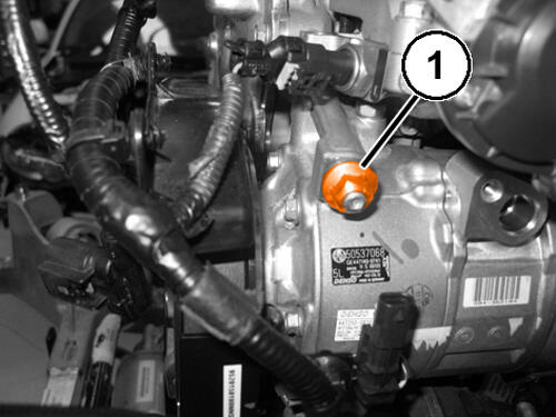
- Remove the upper nut (1) from the A/C compressor.
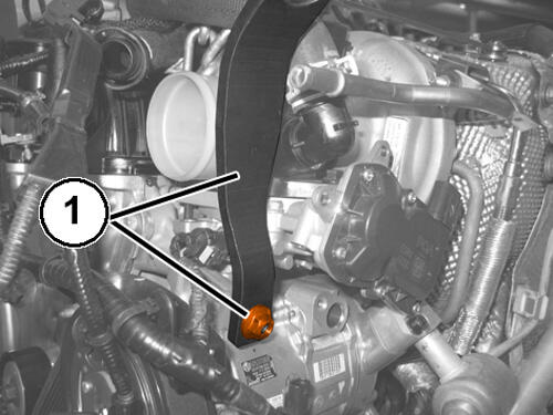
- Install a suitable bracket (1) for lifting the powertrain assembly as shown in the illustration and securely tighten the bolt.
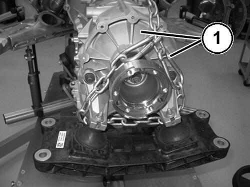
- Secure the transmission unit as shown in the illustration (1).
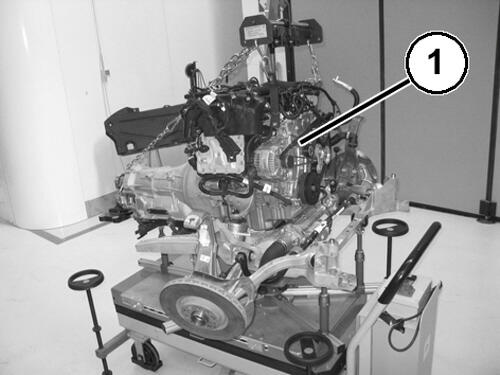
- Using a suitable lift and balance, support the powertrain assembly (1).
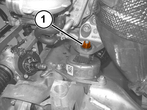
- Working on both sides, remove the nuts (1) securing the engine mount isolator to the bracket.
- Lift and remove the powertrain assembly from the front suspension crossmember and position it on a suitable resting surface.
INSTALLATION
- Using the tools used for removing, lift the power unit and position it on the front suspension crossmember taking care to engage the engine mount isolator pins into their respective holes on the engine brackets.
- Install the nuts securing the engine mount isolator to the bracket and tighten to the proper specification Refer to TORQUE SPECIFICATIONS .
- Remove the tools and the brackets used for lifting the powertrain assembly.
- Install a NEW upper nut securing the A/C compressor and tighten to the proper specification Refer to TECHNICAL SPECIFICATIONS .
- Connect the low pressure EGR solenoid valve wire harness connector.
- Connect the A/C compressor wire harness connector.
- Install the vacuum and fuel vapor lines, securely tighten the bolt of the intermediate bracket and connect the quick connectors.
- Position the automatic transmission wiring harness.
- Using a NEW O-ring, install the transmission fluid pipe.
- Install and securely tighten the thermostat mounting bracket bolts.
- Install the bolt securing the transmission fluid lines to the transmission bell housing and securely tighten.
- Install the bolt securing the transmission fluid lines to the front suspension crossmember and securely tighten.
- Connect the transmission fluid supply and return lines engaging the plate and securely tightening the bolt.
- Connect the solenoid valve assembly wire harness connector and turn the lock ring nut.