Cylinder Head
REMOVAL
- Raise and support the vehicle. Refer to HOISTING, STANDARD PROCEDURE .
- Disconnect and isolate the negative battery cable.
- Drain the engine coolant system. Refer to DRAINING AND FILLING THE ENGINE COOLING SYSTEM .
- Drain the turbocharger coolant system. Refer to DRAINING AND FILLING THE TURBOCHARGER COOLING SYSTEM .
- Recover the A/C refrigerant system. Refer to PLUMBING, STANDARD PROCEDURE .
- Remove the cam chain. Refer to CHAIN AND SPROCKETS, TIMING, REMOVAL AND INSTALLATION .
- Remove the variable valve actuation assembly. Refer to ASSEMBLY, VARIABLE VALVE ACTUATION, REMOVAL AND INSTALLATION .
- Remove the generator. Refer to GENERATOR, REMOVAL AND INSTALLATION .
- Remove the intake manifold. Refer to MANIFOLD, INTAKE, REMOVAL AND INSTALLATION .
- Remove the turbocharger. Refer to TURBOCHARGER, REMOVAL AND INSTALLATION .
- Remove the A/C discharge line. Refer to LINE, A/C DISCHARGE, REMOVAL AND INSTALLATIONLINE, A/C DISCHARGE JUMPER, REMOVAL AND INSTALLATION .
- Remove the A/C compressor. Refer to COMPRESSOR, A/C, REMOVAL AND INSTALLATION
.
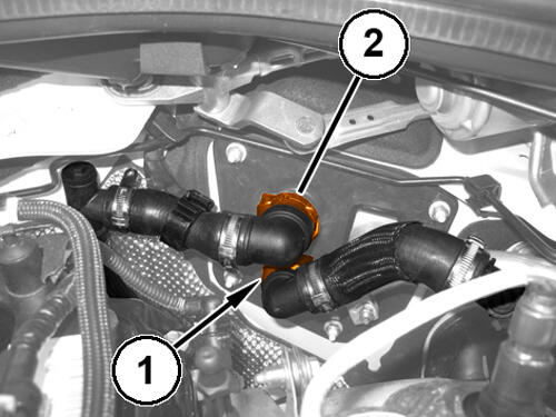
- Disconnect the quick coupling (1) of the water supply pipe from the heater core.
- Disconnect the quick coupling (2) of the water return pipe from the heater core.
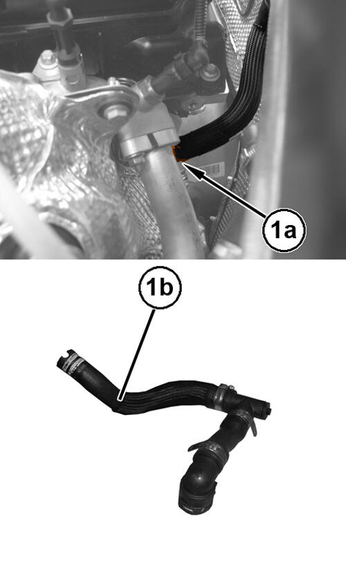
- Loosen the clamp (1a) and remove the water return pipe (1b).
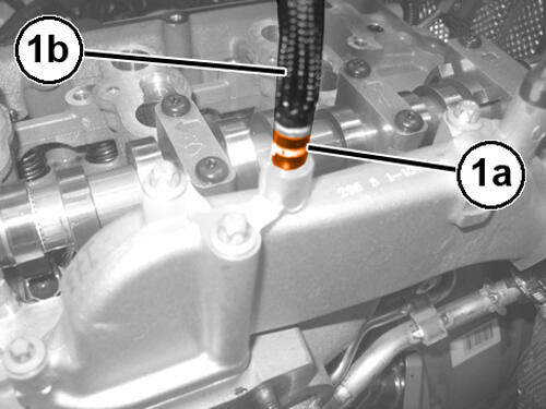
- Loosen the clamp (1a) and disconnect the degassing pipe (1b).
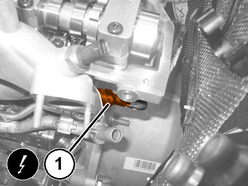
- Disconnect the camshaft position sensor electrical connection (1).
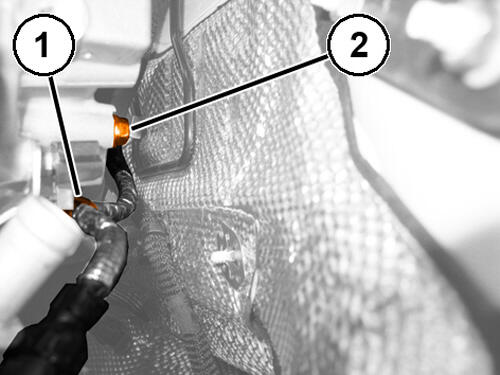
- Release the wiring retaining clip (1).
- Remove the bolt (2) and disconnect the ground cable.
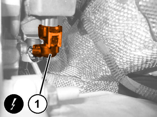
- Disconnect the electrical connection (1) for the fuel pressure regulator.
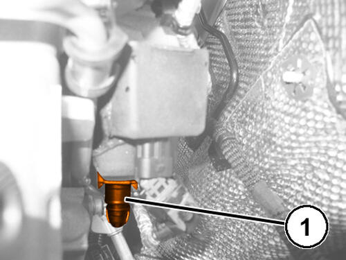
- Disconnect the front fuel supply pipe quick coupling (1) to the high pressure pump.
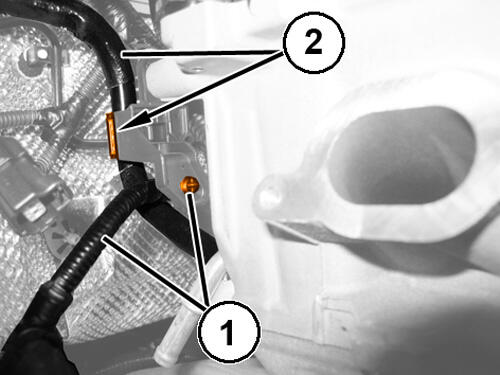
- Release the wiring retaining clip (1) and move it aside.
- Open the retaining clip (2) for the high pressure pump front fuel supply pipe.NOTE:
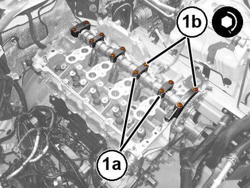
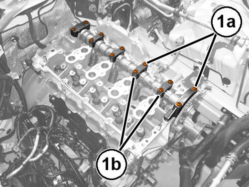
To avoid bending the camshaft, partially loosen each cam cap bolt, one turn at a time, to remove the camshaft caps.
- Remove the bolts (1a) and remove camshaft caps (1b).
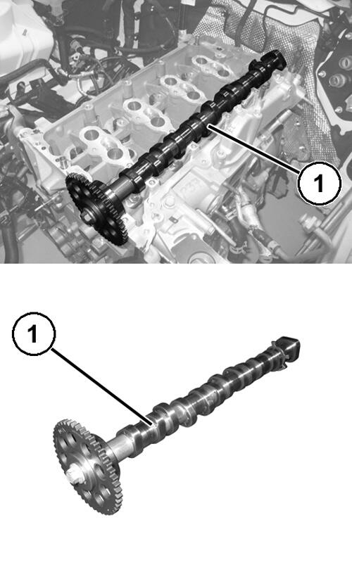
- Remove the camshaft (1) with the camshaft sprocket attached.
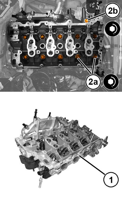
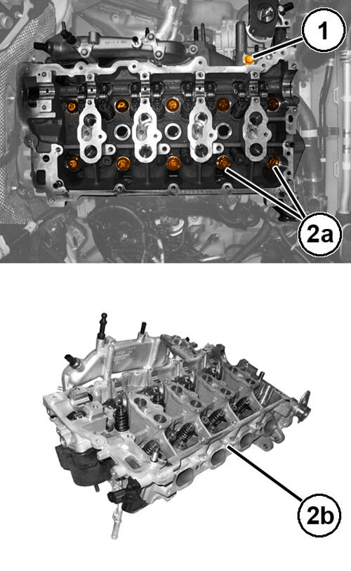
- Remove the side bolt (1) securing the cylinder head to the crankcase.
- Remove the inner bolts (2a) and remove the cylinder head assembly (2b).
- Remove the head gasket from the locating pins.
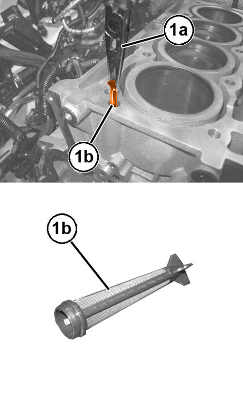
- Using suitable pliers (1a), remove the VVAA oil supply filter (1b).
- Check the locating pins (1).
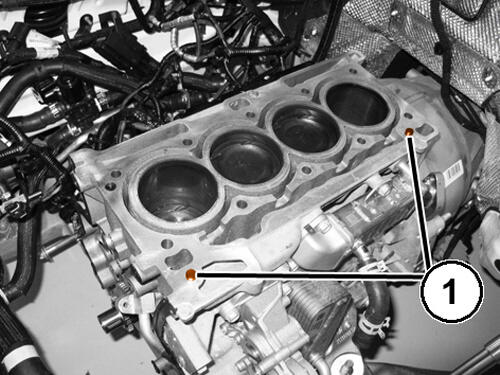
INSTALLATION
- Clean and prepare all engine gasket surfaces. Refer to ENGINE GASKET SURFACE PREPARATION .
- Install the VVAA oil supply filter in the cylinder head.
- Install a new cylinder head gasket.
- Place the complete cylinder head (1) in position.
- Install ten inner head bolts (2a) hand tight.
- Install one outer head bolt (2b) hand tight.
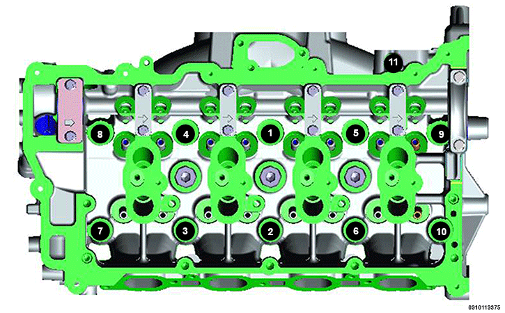
- Tighten the ten inner cylinder head bolts (1 - 10) in the sequence shown, following this 4 step torque plus angle method. Tighten according to the following torque values:
- Step 1: All to 20 N.m (15 ft. lbs.)
- Step 2: All to 55 N.m (40 ft. lbs.)
- Step 3: All again to 55 N.m (41 ft. lbs.)
- Step 4: All an additional 180° Turn Do not use a torque wrench for this step.
- Tighten the one outer cylinder head bolt (11) to 28 N.m (21 ft. lbs.).NOTE:
To avoid bending the camshaft, partially tighten each cam cap bolt, one turn at a time, to seat the camshaft to the head. Do not torque to specification until the cam caps are in full contact with the cylinder head.
- Position the camshaft in the cylinder head, install the camshaft bearing caps (1a) and bolts (1b).
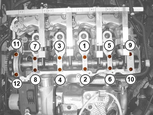
- Tighten the bolts in the sequence shown to the proper specification. Refer to TORQUE SPECIFICATIONS .
- Close the front fuel supply pipe retaining clip to the high pressure pump.
- Refit the wiring and engage it in the retaining clips.
- Connect the front fuel supply pipe quick coupling to the high pressure pump.
- Connect the electrical connection for the fuel pressure regulator.
- Connect the ground cable and tighten the bolt.
- Engage the wiring in the respective retaining clip.
- Connect the camshaft position sensor electrical connection.
- Connect the degassing pipe and close the clamp.
- Install the water return pipe and close the retaining clamp.
- Connect the quick coupling of the water return pipe to the heater core.
- Connect the quick coupling of the water supply pipe to the heater core.
- Install the A/C compressor. Refer to COMPRESSOR, A/C, REMOVAL AND INSTALLATION .
- Install the A/C discharge line. Refer to LINE, A/C DISCHARGE, REMOVAL AND INSTALLATIONLINE, A/C DISCHARGE JUMPER, REMOVAL AND INSTALLATION .
- Install the turbocharger. Refer to TURBOCHARGER, REMOVAL AND INSTALLATION .
- Install the intake manifold. Refer to MANIFOLD, INTAKE, REMOVAL AND INSTALLATION .
- Install the generator. Refer to GENERATOR, REMOVAL AND INSTALLATION .
- Install the variable valve actuation assembly. Refer to ASSEMBLY, VARIABLE VALVE ACTUATION, REMOVAL AND INSTALLATION .
- Install the cam chain. Refer to CHAIN AND SPROCKETS, TIMING, REMOVAL AND INSTALLATION .
- Evacuate and charge the A/C refrigerant system. Refer to PLUMBING, STANDARD PROCEDURE .
- Fill the turbocharger coolant system. Refer to DRAINING AND FILLING THE TURBOCHARGER COOLING SYSTEM .
- Fill the engine coolant system. Refer to DRAINING AND FILLING THE ENGINE COOLING SYSTEM .
- If removed, install the oil filter and fill the engine crankcase with the proper oil to the correct level. Refer to CAPACITIES AND RECOMMENDED FLUIDS, SPECIFICATIONS .
- Connect the negative battery cable.
- Remove the support and lower the vehicle.