Cylinder Head
DISASSEMBLY
- Remove the cylinder head. Refer to CYLINDER HEAD, REMOVAL AND INSTALLATION .
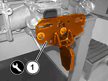
- Install the Cylinder Head Overhaul Support 1860470000 (1) to the turbocharger mounting studs on the cylinder head.
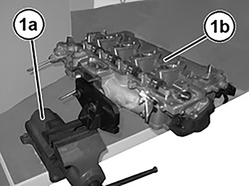
- Position the cylinder head (1b) in the vice (1a).
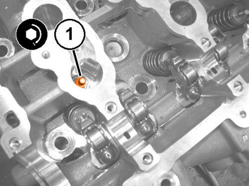
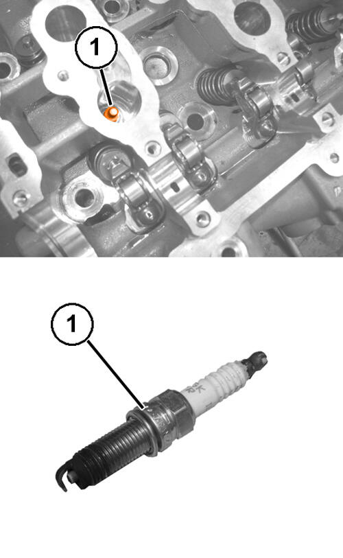
- Remove the spark plugs (1).
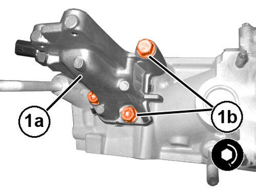
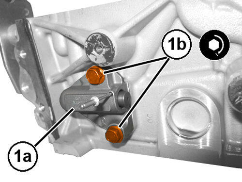
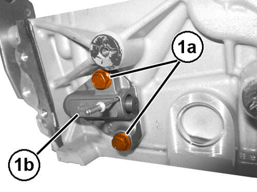
- Remove the bolts (1a) and remove the cam chain tensioner (1b).
- Remove the bolts (1a) and remove the low pressure EGR valve manifold (1b) complete with gasket.
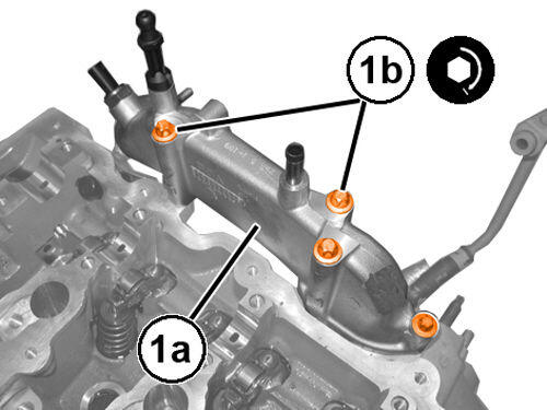
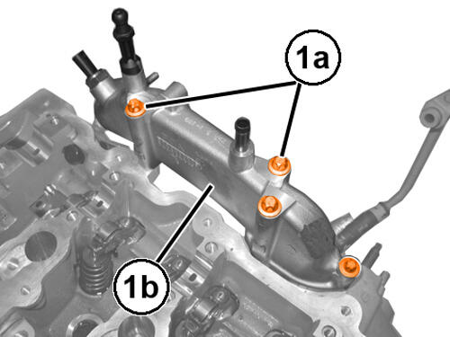
- Remove the bolts (1a) and remove the engine coolant manifold (1b) from the cylinder head complete with gasket.
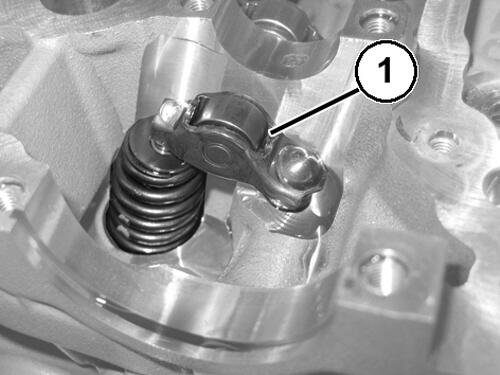
- Remove the hydraulic tappets and rocker arms (1).
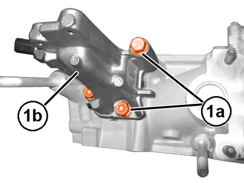
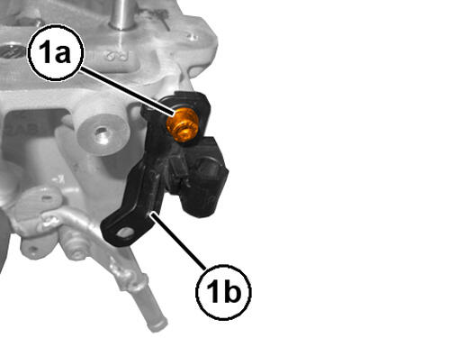
- Remove the bolt (1a) and remove the wiring retaining bracket (1b).
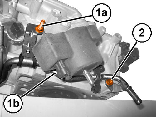
- Remove the stud bolt (1a) securing the tandem return pipe to the engine coolant pump and the supply pipe to the turbocharger (1b).
- Remove the tandem pipe bolt (2) on the intake side.
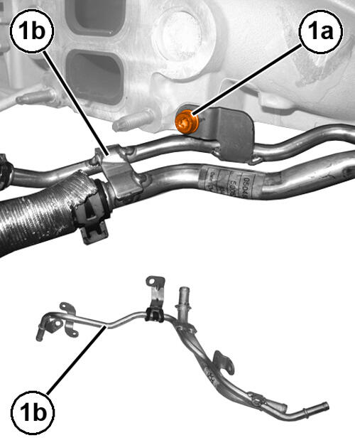
- Remove the bolt (1a) and remove the tandem return pipe to the water pump and the supply pipe to the turbocharger (1b).
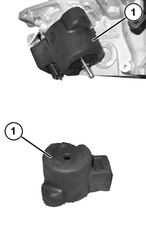
- Remove the pressure pump sound-absorbing shield (1).
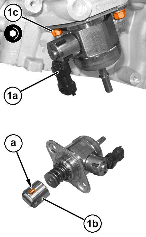
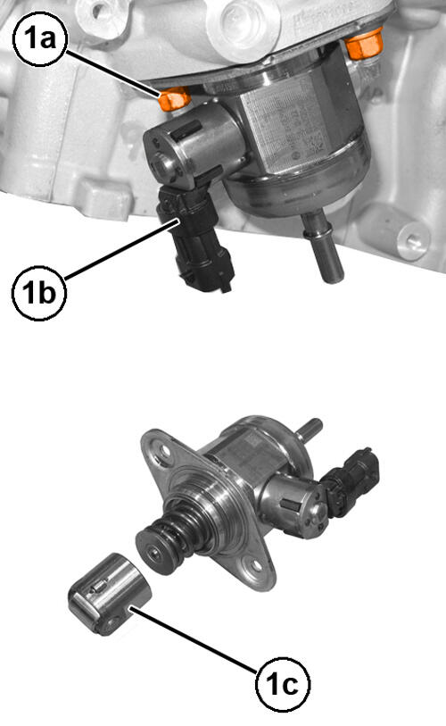
- Remove the nuts (1a) and remove the high pressure pump (1b) complete with roller tappet (1c).
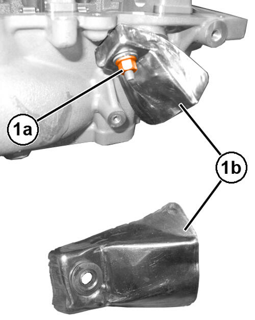
- Remove the nut (1a) and remove the heat shield (1b) from the camshaft position sensor.
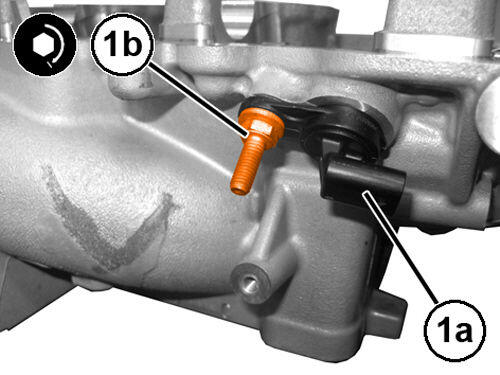
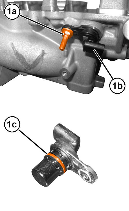
- Remove the stud bolt (1a) and remove the camshaft position sensor (1b) complete with O-ring (1c).
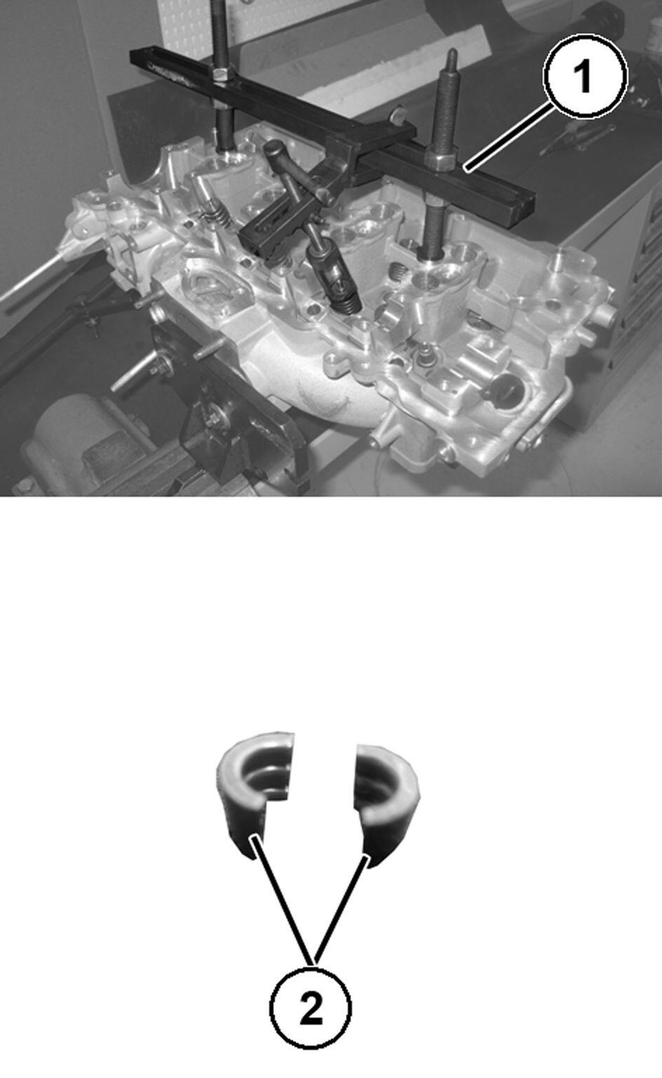
- Position a valve spring compressor (1) on the cylinder head to compress the valve springs and remove the valve retaining locks (2).
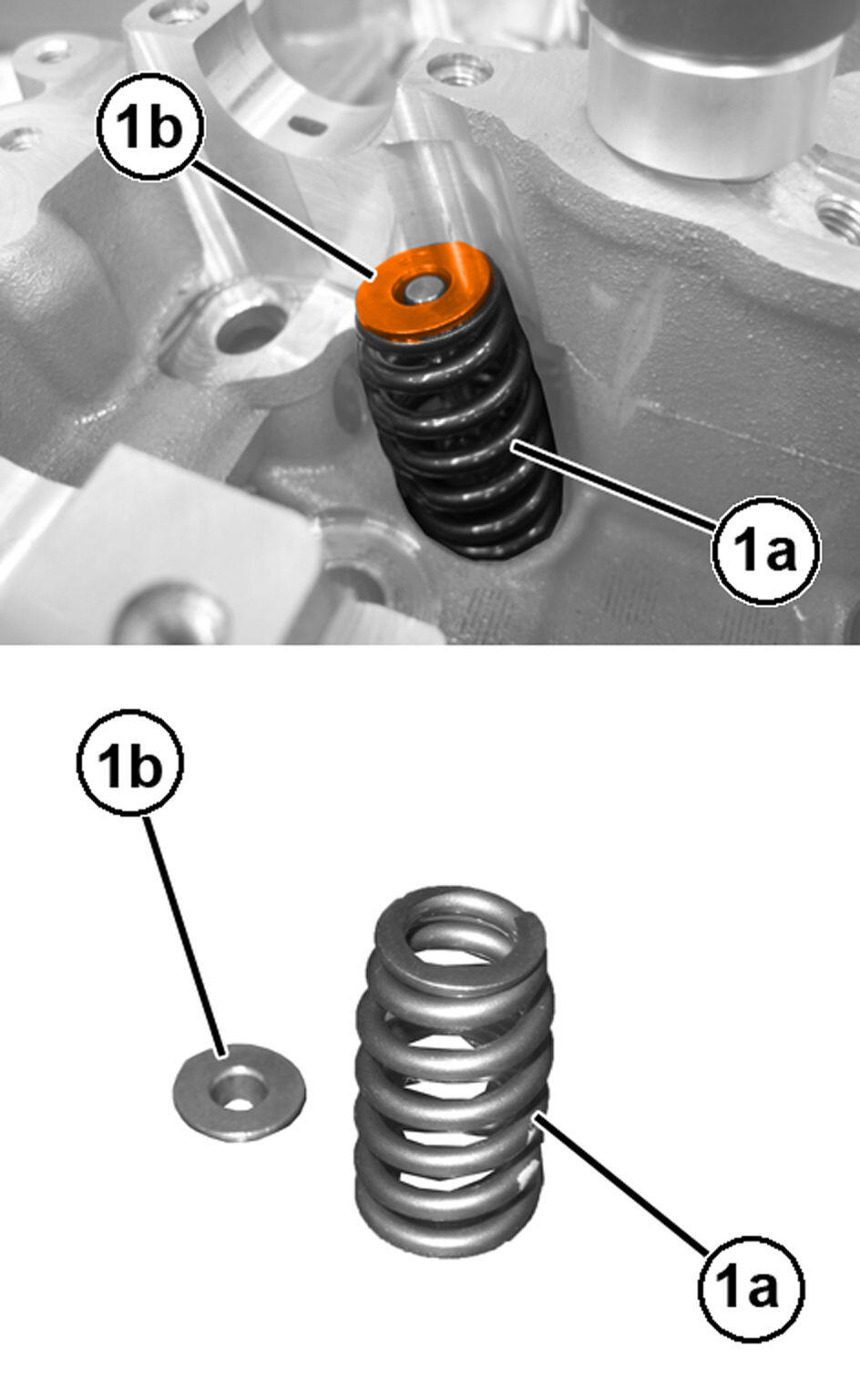
- Release the valve spring compression and remove the valve spring retainer (1b) and valve spring (1a).
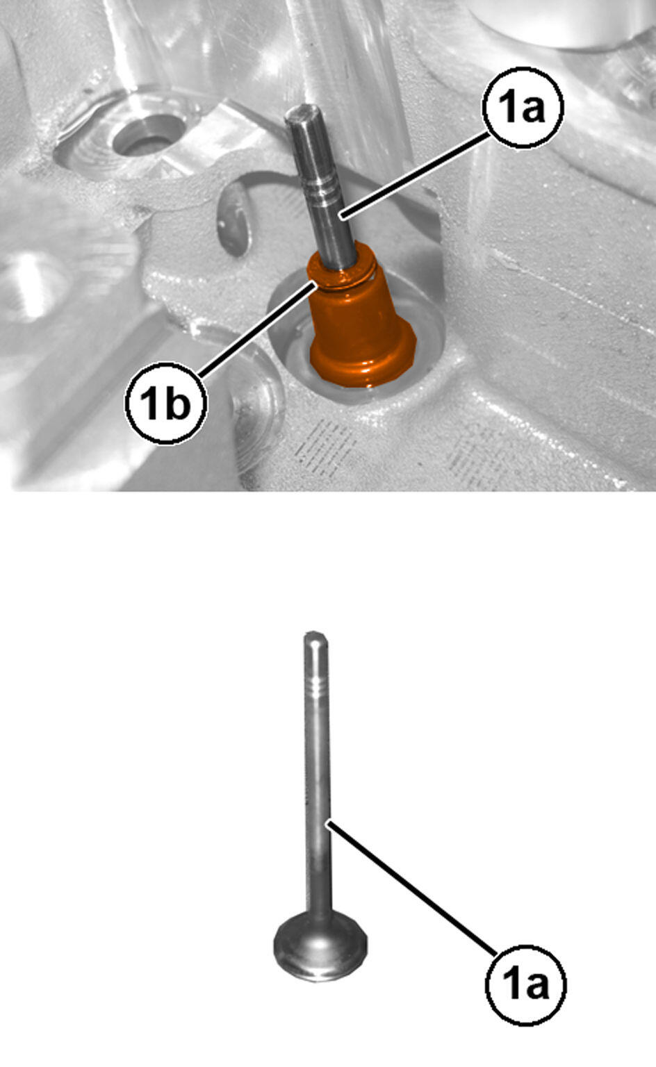
- Remove the valve (1a) and the valve guide seal (1b).
- Repeat the procedure for each valve being removed.
ASSEMBLY
- Remove deposits and clean the valve seats and ports.
- Clean any gasket residues from the lower cylinder head surface.
- Check that the valve stem does not show signs of grooves or seizing.
- Replace valves with a stem diameter that is not within specification. Refer to SPECIFICATIONS .
- Replace valves with a head diameter that is not within specification. Refer to SPECIFICATIONS .
- Replace valve springs that are not within specification. Refer to SPECIFICATIONS .
- Install new valve guide seals.
- Install the valves, springs, spring retainers and retaining locks with the same tools used for disassembly.
- Install the camshaft position sensor (1a), complete with new O-ring, and tighten the stud bolt (1b) to the proper specification Refer to TORQUE SPECIFICATIONS .
- Install the camshaft position sensor heat shield and tighten the nut.CAUTION:
To avoid side loading damage to the pump during assembly, the nuts need to be run down at the same time, or in alternating one half turn increments. Do not torque to specification until the mounting flange is in full contact with the cylinder head.
- Lubricate the roller tappet (1b) with engine oil.
- Install the high pressure pump (1a) complete with roller tappet (1b) onto the cylinder head and tighten the nuts (1c) to the proper specification Refer to TORQUE SPECIFICATIONS
.NOTE:
The side anti-rotation roller "a" must be inserted in the groove on the cylinder head.
- Install the sound-absorbing shield on the pressure pump.
- Install the tandem return pipe to the engine coolant pump and the supply pipe to the turbocharger and tighten the bolt on intake side and the stud bolt on the exhaust side.
- Tighten the bolt securing the tandem return pipe to the engine coolant pump and the supply pipe to the turbocharger.
- Install the wiring retainer and tighten the bolt.
- Install the hydraulic tappets in the cylinder head.
- Install the engine coolant manifold (1a) on the cylinder head, complete with a new gasket, and tighten the bolts (1b) to the proper specification Refer to TORQUE SPECIFICATIONS
.
- Install the low pressure EGR valve manifold (1a), complete with the new gasket, and tighten the bolts (1b) to the proper specification Refer to EXHAUST GAS RECIRCULATION, TECHNICAL SPECIFICATIONS
.
- Install the cam chain tensioner (1a) with its piston secured in the retracted position and tighten the bolts (1b) to the proper specification Refer to TORQUE SPECIFICATIONS
.
- Install the spark plugs and tighten them to the proper specification Refer to TECHNICAL SPECIFICATIONS .
- Remove the cylinder head from the Cylinder Head Overhaul Support 1860470000.
- Install the cylinder head. Refer to CYLINDER HEAD, REMOVAL AND INSTALLATION .