Cylinder Head Cover
REMOVAL
- Disconnect and isolate the negative battery cable.
- Remove the fuel injectors. Refer to INJECTOR(S), FUEL, REMOVAL AND INSTALLATION .
- Remove the ignition coils. Refer to COIL, IGNITION, REMOVAL AND INSTALLATION
.
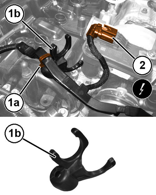
- Release the clip (1a) retaining the engine compartment wiring harness channel and remove the mount (1b).
- Disconnect the turbocharger actuator wire harness connection (2).
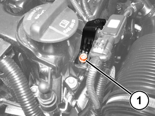
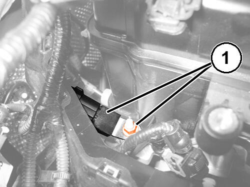
- Remove the bolt (1) and remove the oil vapor pressure sensor mounting bracket.
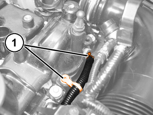
- Release the wiring retaining clips (1) at the intake side, rear and center of the cylinder head cover.
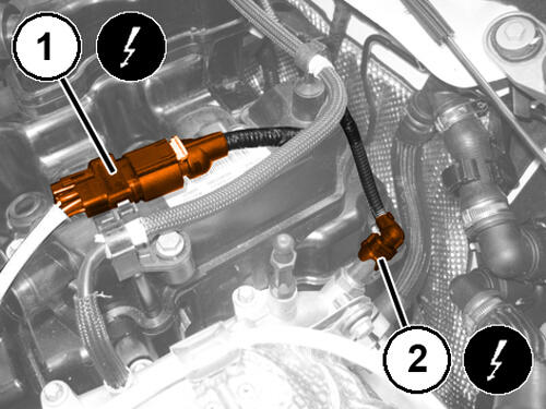
- Release the clip and disconnect the upstream oxygen sensor wire harness connection (1).
- Disconnect the engine coolant temperature sensor wire harness connection (2).
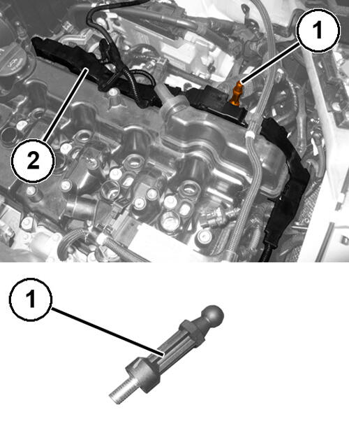
- Remove the engine cover ball stud (1).
- Release the engine compartment wiring harness channel (2) from the retaining clips and move it aside.
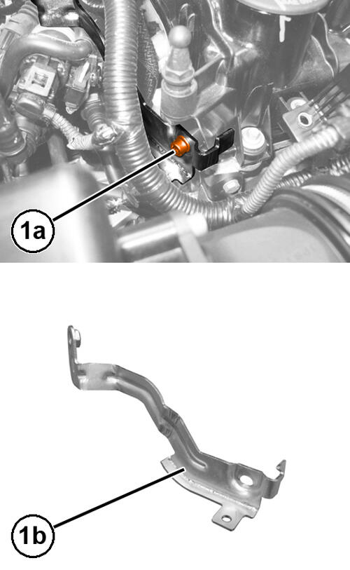
- Remove the bolt (1a) and remove the heat exchanger shield retaining bracket (1b).
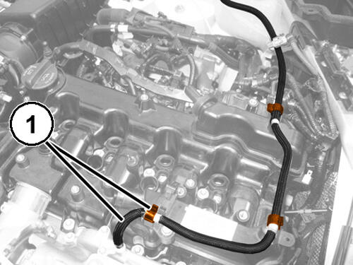
- Open the clips (1) and release the degassing pipe.
- 1. Remove the nut (1) and reposition the ignition coil capacitor.
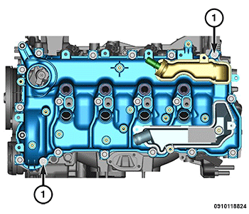
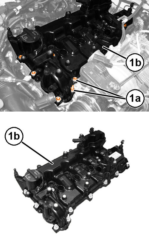
- Remove seventeen bolts and two stud-bolts (1a) and remove the cylinder head cover (1b).
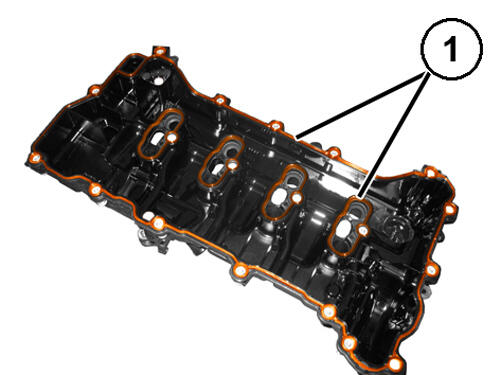
- Remove the sealant residues and the gaskets (1) from the cylinder head cover.
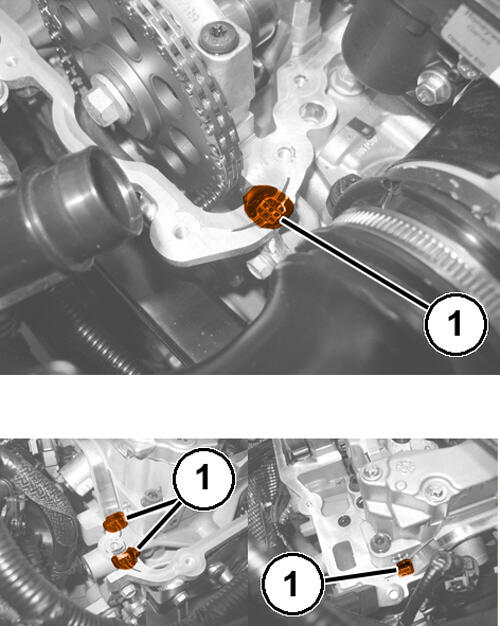
- Remove the sealant residues (1) from the four T-joint locations on the cylinder head.
INSTALLATION
- Clean the cylinder head cover sealing surfaces with isopropyl alcohol in preparation for sealant application.CAUTION:
Engine assembly requires the use of a unique sealant that is compatible with engine oil. Using a sealant other than Mopar® Threebond Engine RTV Sealant may result in engine fluid leakage.
CAUTION:Following the application of Mopar® Threebond Engine RTV Sealant to the gasket surfaces, the components must be assembled within 10 minutes and the attaching fasteners must be tightened to specification within 45 minutes. Prolonged exposure to the air prior to assembly may result in engine fluid leakage.
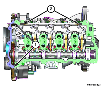
- Apply a 2 to 3 mm wide bead of Mopar® Threebond Engine RTV Sealant to the cylinder head cover sealing surface in four places:
- Front cover/cylinder head T-joint (1).
- Variable Valve Actuator Assembly (VVAA)/cylinder head T-joint (2).
- Install the cylinder head cover to the cylinder head with seventeen bolts and two stud-bolts (1) hand tight.
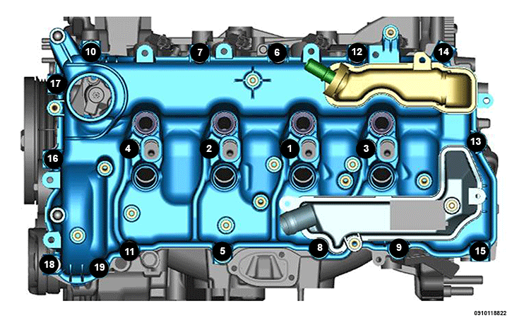
- Tighten the seventeen bolts and two stud-bolts in the sequence shown to the proper specification Refer to TORQUE SPECIFICATIONS .
- Install the ignition coil capacitor and tighten the nut.
- Engage the degassing pipe and close the retaining clips.
- Install the heat exchanger shield bracket and tighten the bolt.
- Install the engine compartment wiring harness channel and engage it the retaining clips.
- Install the engine cover ball stud and tighten it.
- Connect the electrical connection for the engine coolant temperature sensor.
- Connect the electrical connection for the oxygen sensor and engage it in the retaining clip.
- Engage the engine wiring in the respective retaining clips.
- Install the oil vapor pressure sensor mounting bracket and tighten the bolt.
- Connect the turbocharger actuator electrical connection.
- Install the mount and engage the clips retaining the engine compartment wiring harness channel.
- Install the ignition coils. Refer to COIL, IGNITION, REMOVAL AND INSTALLATION .
- Install the fuel injectors. Refer to INJECTOR(S), FUEL, REMOVAL AND INSTALLATION .
- Connect the negative battery cable.