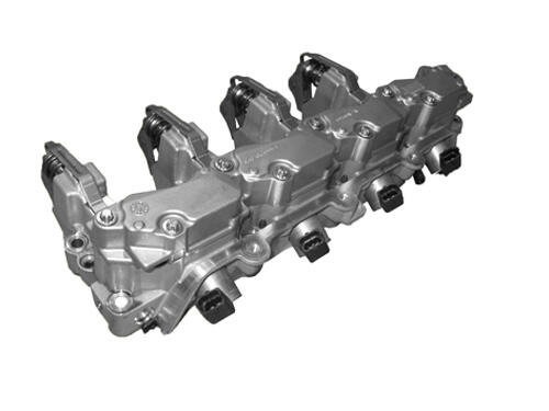
Variable Valve Actuation Assembly
REMOVAL
- Remove the cylinder head cover. Refer to COVER(S), CYLINDER HEAD, REMOVAL AND INSTALLATION .
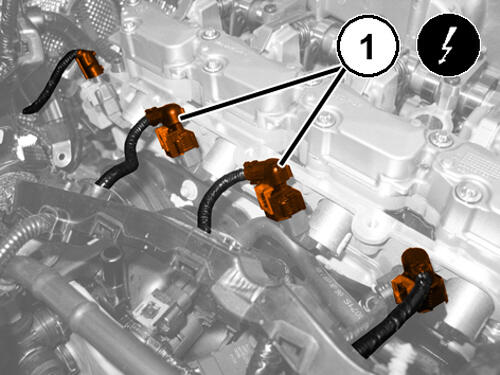
- Unlock and disconnect the oil temperature sensor harness connector (1).
- Unlock and disconnect the four Variable Valve Actuation Assembly (VVAA) wire harness connectors (1).
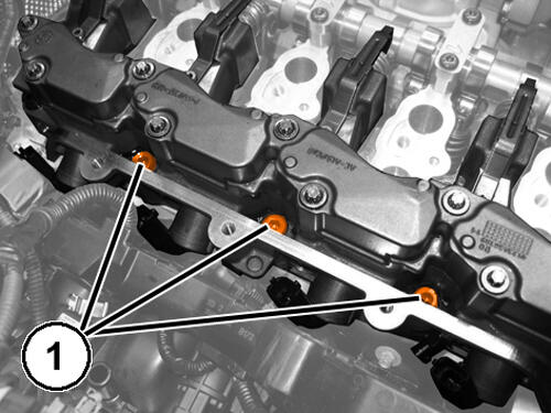
- Remove the thee indicated bolts (1) from the VVAA.NOTE:
These bolts need to be removed prior to the installation of the Spring Compressor tool. Once in place, the tool obstructs access to these bolts.
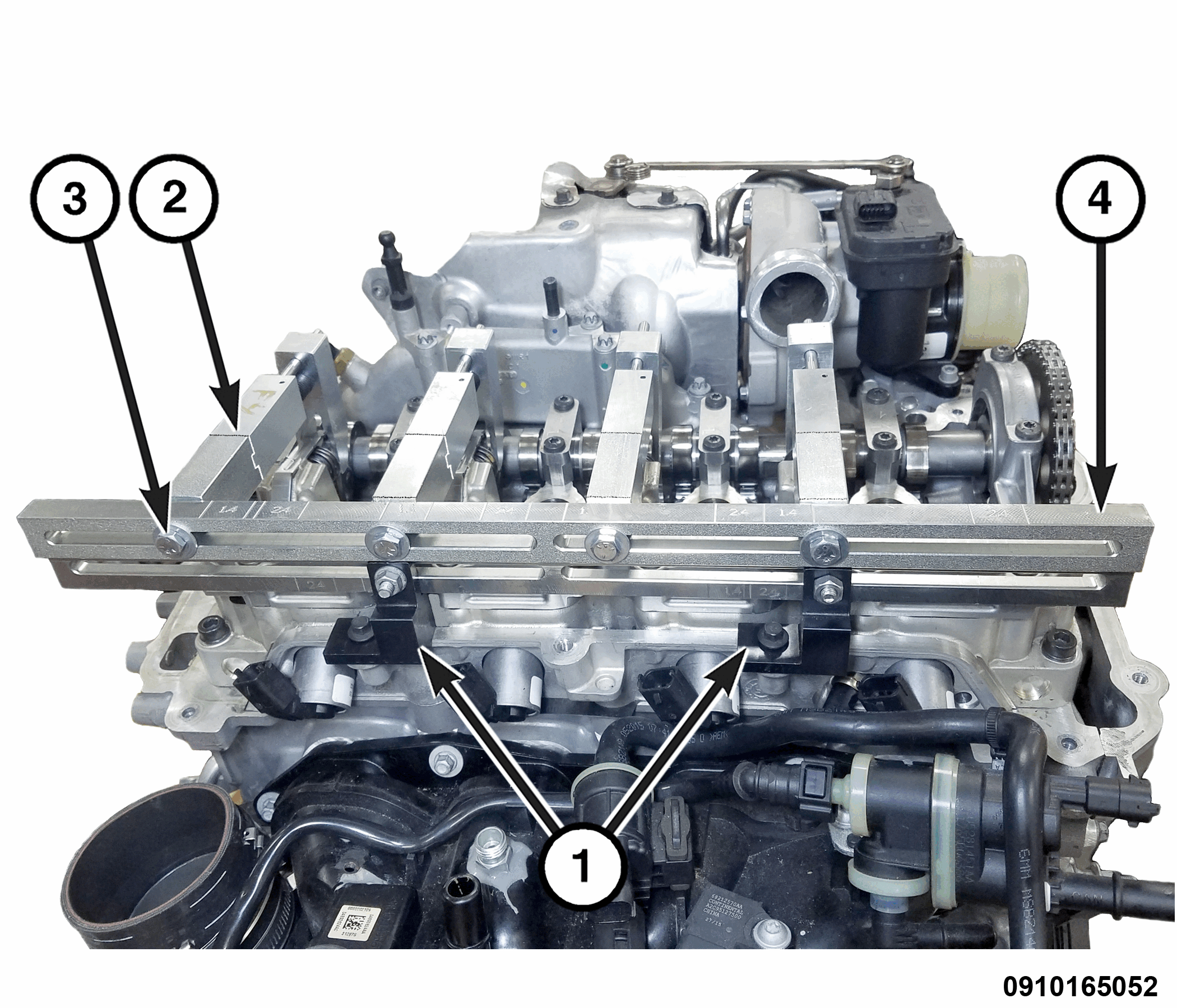
- Assemble the (special tool #2027207090, Tab, 90 Degree) (1) and (special tool #2027204090, Adapter, Stand-Off) (2) with the (special tool #2027212090, Bolt, Stand-Off Adapter) (3) to the (special tool #10259B, Compressor, MultiAir® Spring) (4) or the UNIAIR Module Compression Plate 2020000090.
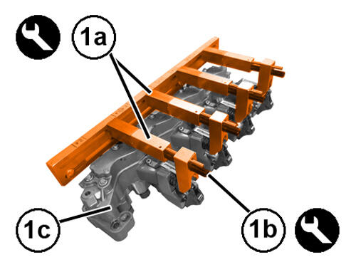
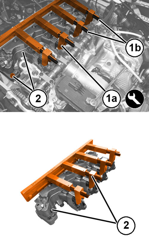
- Position the tool (1a) and tighten the screws (1b) to compress the springs on the variable valve actuation assembly (VVAA).
- Remove the remaining bolts (2) from the VVAA.
- Remove the VVAA, with the tools attached, from the cylinder head.CAUTION:
Do not invert the variable valve actuation assembly when it is removed from the engine. Oil will drain from the assembly and excessive engine cranking will be required to refill the assembly and start the engine.
- Set the assembly on two blocks to store during repairs.NOTE:
Be sure to store the assembly in the upright position AT ALL TIMES to prevent oil related issues within the assembly.
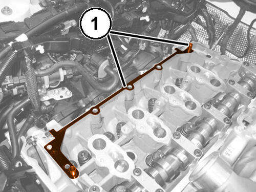
NOTE:There are two locating dowel pins (1) that properly position the VVAA to the cylinder head. Be careful that both dowels remain installed in the cylinder head after removing the VVAA. If a dowel comes loose, locate the missing dowel and DISCARD it. Install a NEW dowel. DO NOT REUSE A DOWEL THAT HAS BEEN REMOVED FROM THE CYLINDER HEAD.
- Remove and DISCARD the VVAA gasket (1). Remove any residual gasket material and sealant from the VVAA, cylinder head and cylinder head cover. Refer to ENGINE GASKET SURFACE PREPARATION .
- If required, remove the rocker arms from the VVAA. Refer to ROCKER ARM, VALVE, REMOVAL AND INSTALLATION .
- If required, remove the oil temperature sensor from the VVAA. Refer to SENSOR, OIL TEMPERATURE, REMOVAL AND INSTALLATION .
INSTALLATION
- If removed, install the oil temperature sensor to the Variable Valve Actuation Assembly (VVAA). Refer to SENSOR, OIL TEMPERATURE, REMOVAL AND INSTALLATION .
- If removed, install the rocker arms to the VVAA. Refer to ROCKER ARM, VALVE, REMOVAL AND INSTALLATION .
- If the locating dowel pins were removed, install two NEW VVAA dowels.
- Install a NEW
VVAA gasket.
- Assemble the (special tool #2027207090, Tab, 90 Degree) (1) and (special tool #2027204090, Adapter, Stand-Off) (2) with the (special tool #2027212090, Bolt, Stand-Off Adapter) (3) to the (special tool #10259B, Compressor, MultiAir® Spring) (4) or the UNIAIR Module Compression Plate 2020000090.CAUTION:
Do not invert the variable valve actuation assembly when it is removed from the engine. Oil will drain from the assembly and excessive engine cranking will be required to refill the assembly and start the engine.
- Position the tool (1a) and tighten the screws (1b) to compress the springs on the VVAA (1c).
- Install the VVAA and the accessible VVAA retaining bolts hand tight.
- Remove the tools used to compress the springs on the VVAA.
- Install the remaining VVAA retaining bolts hand tight.
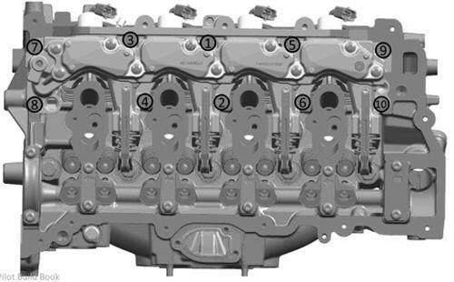
- Tighten the ten VVAA retaining bolts in the sequence shown to the proper specification Refer to TORQUE SPECIFICATIONS .
- Connect and lock the four VVAA wire harness connectors.
- Connect and lock the oil temperature sensor wire harness connector.
- Install the cylinder head cover. Refer to COVER(S), CYLINDER HEAD, REMOVAL AND INSTALLATION .
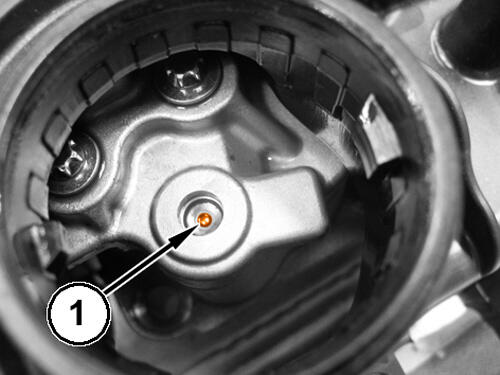
- Use a graduated syringe to press the valve ball (1) on the VVAA module and top up oil of the prescribed type. Refer to CAPACITIES AND RECOMMENDED FLUIDS, SPECIFICATIONS
.NOTE:
The oil quantity for the first filling is 200-250 ml.
NOTE:Use new oil only; any residues present in the oil may cause damage to the VVAA actuators.
NOTE:10 ml of oil must remain in the syringe to prevent the introduction of air into the VVAA module.
- Manually rotate the engine crankshaft one complete revolution after having filled the VVAA module.
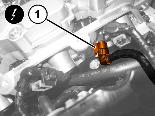
- Install the vapor line from solenoid valve to air intake chamber. Refer to LINES, FUEL VAPOR, REMOVAL AND INSTALLATION .
- Install the side and top engine covers. Refer to COVER, ENGINE, REMOVAL AND INSTALLATION .
- Connect the negative battery cable.