Standard Procedure - Connecting Rod Bearing Fitting
Bearing oil clearance can also be determined by using Plastigage or equivalent. Refer to ENGINE BLOCK, STANDARD PROCEDURE .
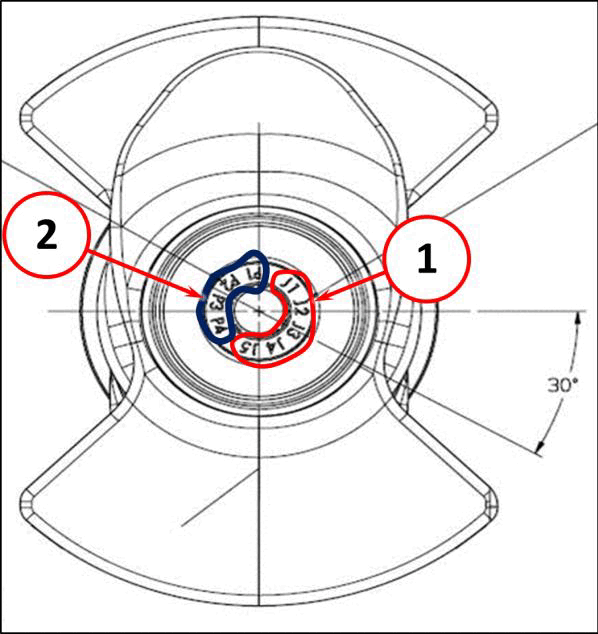
The connecting rod bearings are "select fit" to achieve proper oil clearance. Connecting rod bearing journal diameter grade markings (2) are stamped into the nose of the crankshaft. These marks are read from right to left (counterclockwise), corresponding with journal number 1, 2, 3, 4 and represent specific journal diameters. Refer to SPECIFICATIONS .
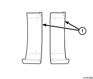
Install the rod bearings in pairs. Do not mix sizes or use a new bearing half with an old bearing half.
Select the bearing size that corresponds to the crankshaft markings for each rod bearing journal. The connecting rod bearing shells (1) are marked with a color code indicating bearing size. The bearings are available in three different sizes in order to achieve the desired oil clearance.
The chart below identifies the three connecting rod bearing sizes.
| Bearing Marking | Size mm (in.) |
|---|---|
| A (Red) | 1.497 - 1.500 mm (0.0589 - 0.0591 in.) |
| B (Blue) | 1.500 - 1.503 mm (0.0591 - 0.0592 in.) |
| C (Yellow) | 1.503 - 1.506 mm (0.0592 - 0.0593 in.) |