Description And Operation
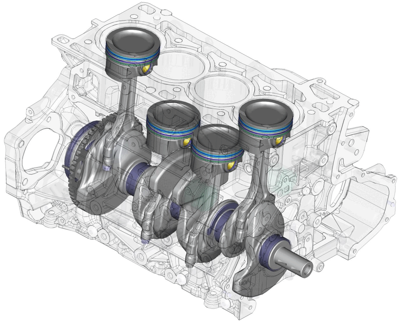
The engine drive components are designed to reduce overall rotational friction forces.
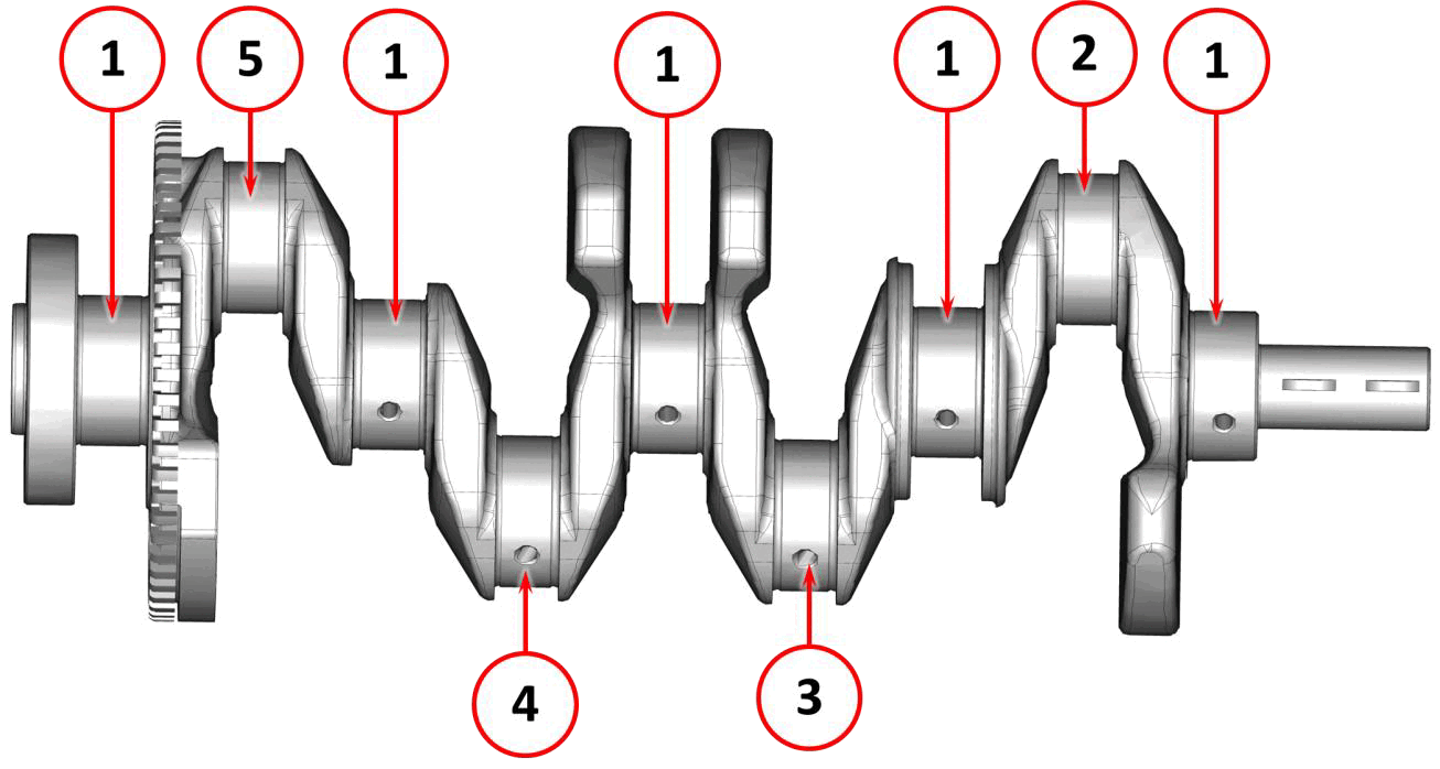
The crankshaft is made of steel and has 5 main journals, 4 crank pins and 4 counterweights. The main journals are numbered starting from the timing side (1st cylinder):
- Main journals
- 1st cylinder crank pin
- 2nd cylinder crank pin
- 3rd cylinder crank pin
- 4th cylinder crank pin
The nominal main journal diameter is: 50 mm. The nominal crank pin diameter is: 50 mm.
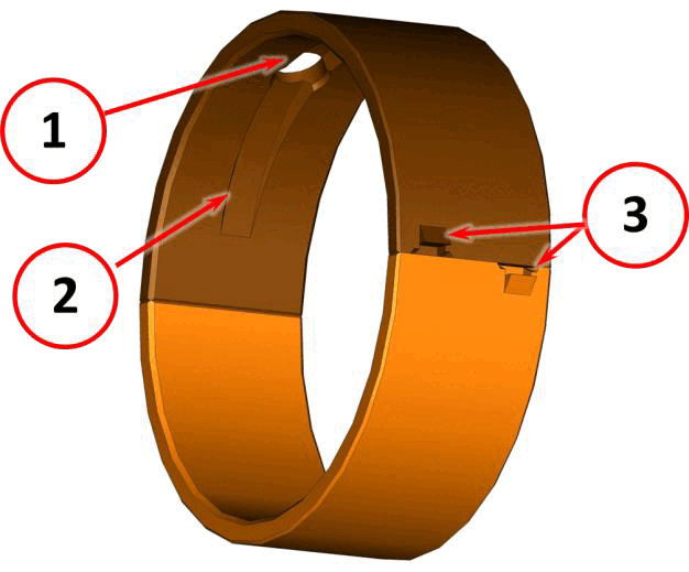
The crankshaft main journals rotate on main bearings located in the engine block. Aluminum alloy half-bearings are used (upper and lower) to reduce dragging friction. Along the outside diameter of the upper half-bearing, there is a hole (1) to allow engine oil to enter. Along the inside diameter there is the groove (2) that allows lubrication of the crankshaft main journal and provides oil to the crank pin lubrication cross-drillings. On both the half-bearings there is the centering "tang" (3).
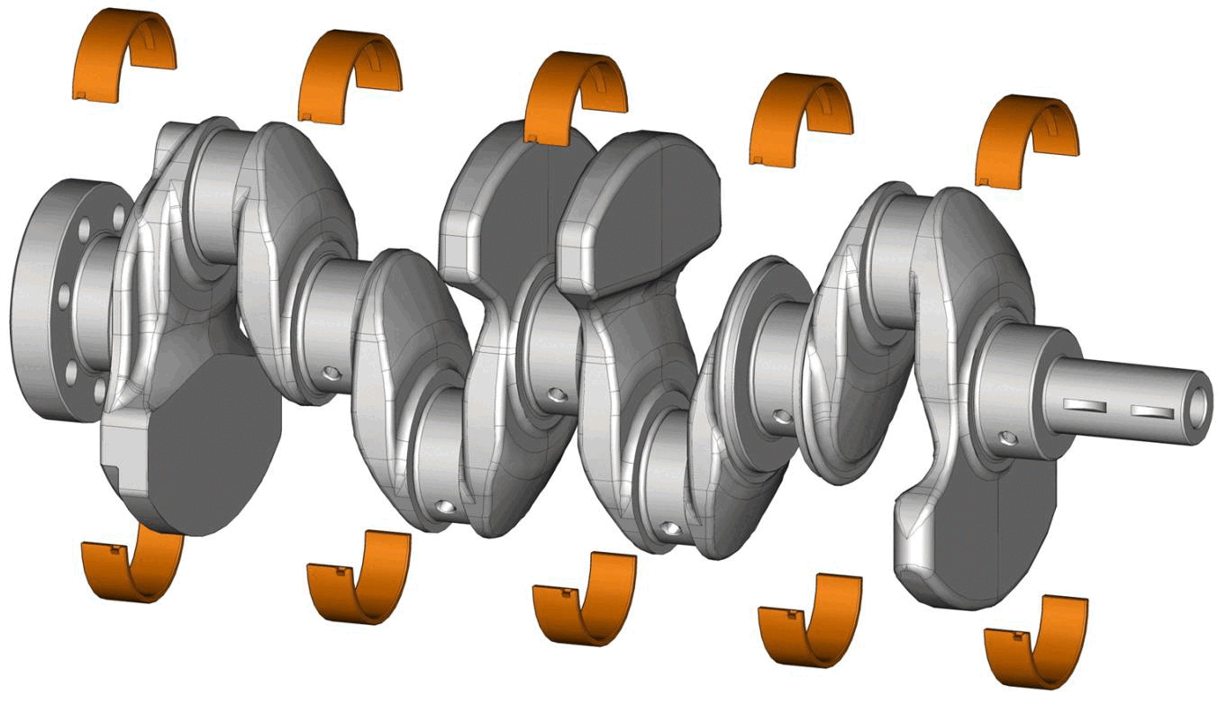
The upper half-bearing has three tolerance classes identified by a number. The number is stamped on the outside surface. The lower half-bearing has 5 tolerance classes, also identified with a number stamped on the outside surface.
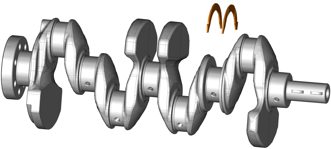
The crankshaft axial clearance is adjusted by two half-rings located at the 2nd main journal.
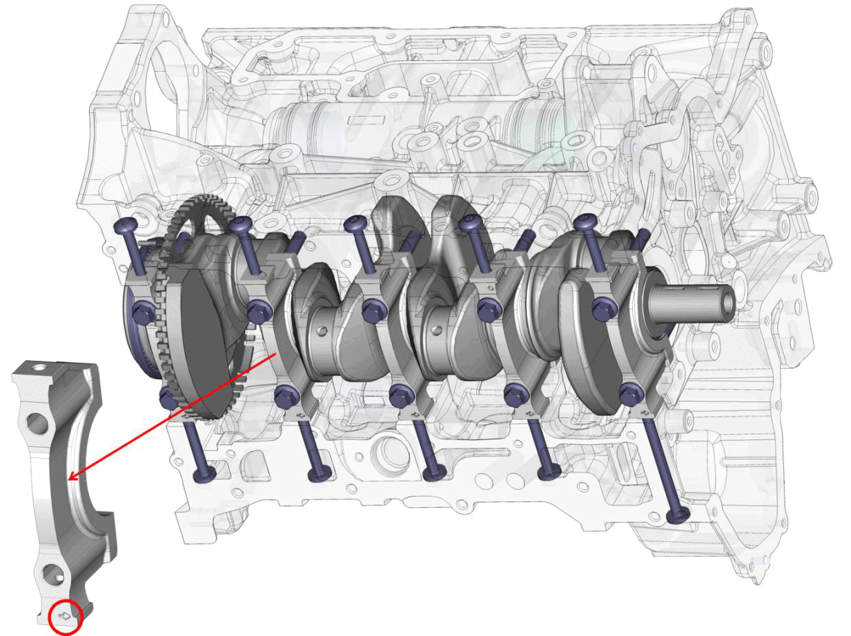
The crankshaft is supported from underneath by five main bearing caps. These are anchored to the engine block by two rows of bolts at the center (ten in total) and by two rows of bolts at the sides (ten in total).
An arrow stamped on the lower surface of each main bearing cap indicates the direction in which the bearing cap should be mounting on the engine block. The bearing cap must be mounted with the arrow pointing towards the timing side.
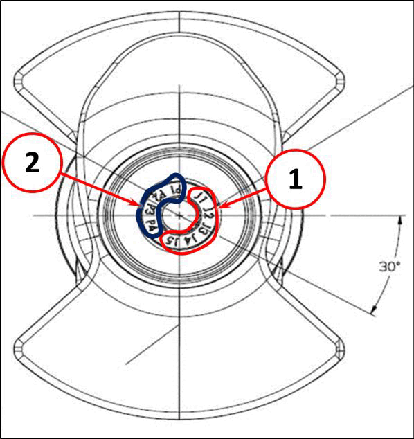
Data regarding the following bearing tolerance classes can be found on the front of the crankshaft (timing side):
- Lower crankshaft main bearing tolerance classes
- Connecting rod big end bearing tolerance classes
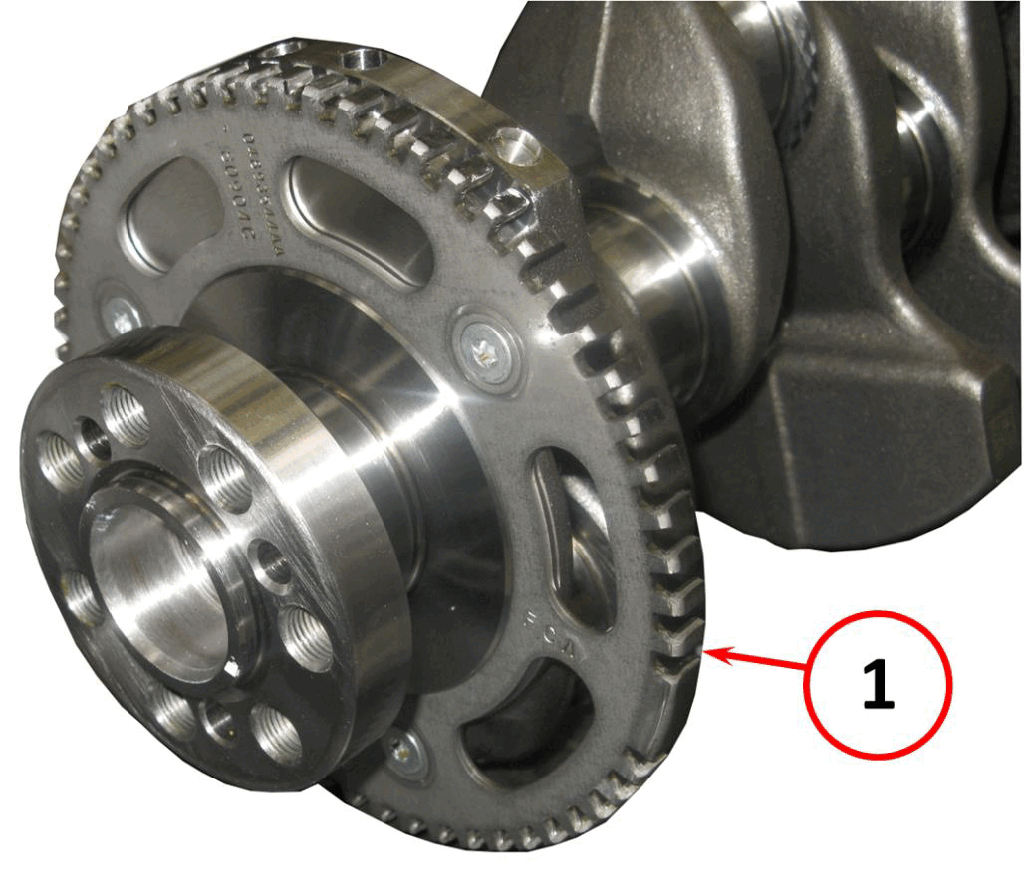
On the crankshaft counterweight next to the fifth main bearing, there is a crankshaft target wheel (1) with the Crankshaft Position (CKP) sensor facing it.
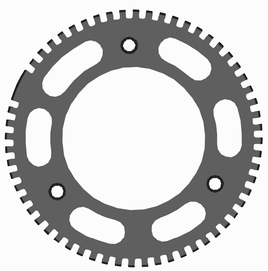
The crankshaft target wheel is fastened to the crankshaft counterweight with 3 screws. The crankshaft target wheel has 57 teeth around its circumference and one tooth that is the width of 3 teeth plus their related spacing.