Removal And Installation: Crankshaft: Removal
- Remove the engine from the vehicle and mount the engine in the maintenance stand. Refer to REMOVAL AND INSTALLATION .
- Remove the ignition coils and spark plugs. Refer to SPARK PLUG, REMOVAL AND INSTALLATION .
- Remove the rear crankshaft oil seal retainer. Refer to SEAL, CRANKSHAFT OIL, REAR, REMOVAL AND INSTALLATION .
- Install the (special tool #1860815000, Tool, Crankshaft Rotating) to the crankshaft.
- Remove the crankshaft sprocket. Refer to CHAIN AND SPROCKETS, TIMING, REMOVAL AND INSTALLATION .
- Remove the right and left engine mount brackets. Refer to BRACKET, ENGINE MOUNT, LEFT, REMOVAL AND INSTALLATION BRACKET, ENGINE MOUNT, RIGHT, REMOVAL AND INSTALLATION BRACKET, ENGINE MOUNT, REAR, REMOVAL AND INSTALLATION .
- Remove the oil pump pick-up and windage tray. Refer to PAN, OIL, REMOVAL AND INSTALLATION .
- If piston or connecting rod replacement is necessary, remove the cylinder head. Refer to CYLINDER HEAD, REMOVAL AND INSTALLATION .
- Remove the crankshaft position sensor. Refer to SENSOR, CRANKSHAFT POSITION, REMOVAL AND INSTALLATION
.CAUTION:
DO NOT use a number stamp or a punch to mark connecting rods. Damage to connecting rod could occur.
NOTE:Connecting rods and bearing caps are not interchangeable and should be marked before removing to ensure correct reassembly.
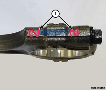
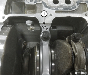
- Mark connecting rod and bearing cap positions (1) using a permanent ink marker or scribe tool.NOTE:
Special care is necessary when handling the joint separating upper and lower halves of the connecting rod. This fractured surface is sensitive and easily damaged, preventing proper reassembly of the cap to the rod. Avoid touching the fractured surfaces and contact with any other work surfaces. Under no circumstances should these surfaces be brushed. It is critical that the joint not be altered in any way during disassembly and assembly.
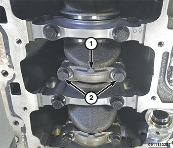
- Remove all connecting rod cap bolts (2) and caps (1) with bearings. Discard the cap bolts (2).CAUTION:
DO NOT use a number stamp or a punch to mark main bearing caps, as damage to main bearings could occur.
NOTE:Main bearing caps (1) are not interchangeable and are marked to insure correct assembly.
- Mark the main bearing cap positions (1) using a permanent ink marker or a scribe tool.
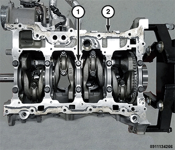
- Remove the ten main bearing cap bolts (1) and ten main bearing tie bolts (2).
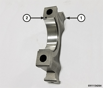
- Remove the main bearing caps (1) with bearings (2).
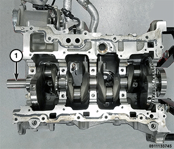
- Lift the crankshaft (1) from the cylinder block. Do not damage the main bearings or journals when removing the crankshaft.
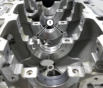
- If required, remove the thrust bearings (1).
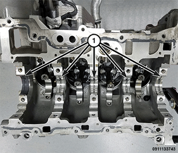
- If required, remove the upper main bearings (1).
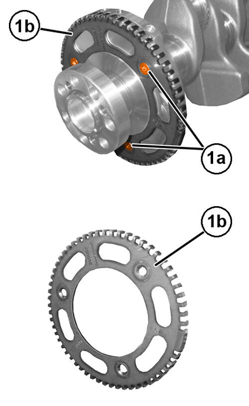
- If required, remove the screws (1a) and remove the target wheel (1b) from the crankshaft.