Intake Manifold
REMOVAL
- Raise and support the vehicle. Refer to HOISTING, STANDARD PROCEDURE .
- Disconnect and isolate the negative battery cable.
- Drain the turbocharger cooling system. Refer to DRAINING AND FILLING THE TURBOCHARGER COOLING SYSTEM .
- Remove the top engine cover. Refer to COVER, ENGINE, REMOVAL AND INSTALLATION COVER, ENGINE, REMOVAL AND INSTALLATION .
- Remove the engine belly pan. Refer to BELLY PAN, ENGINE, REMOVAL AND INSTALLATION .
- Remove the Mass Airflow (MAF) sensor. Refer to SENSOR, MASS AIRFLOW (MAF), REMOVAL AND INSTALLATION .
- Remove the air filter housing. Refer to BODY, AIR CLEANER, REMOVAL AND INSTALLATION .
- Remove the side engine cover. Refer to COVER, ENGINE, REMOVAL AND INSTALLATION .
- Remove the engine oil vapor intake pipe. Refer to SEPARATOR, OIL, REMOVAL AND INSTALLATION .
- Remove the air outlet pipe from turbocharger to throttle body. Refer to COOLER AND HOSES, CHARGE AIR, REMOVAL AND INSTALLATION .
- Remove the Powertrain Control Module (PCM) and PCM mounting bracket. Refer to MODULE, POWERTRAIN CONTROL (PCM), REMOVAL AND INSTALLATION .
- Remove the intake air pressure/temperature sensor. Refer to SENSOR, TMAP-INTAKE MANIFOLD, REMOVAL AND INSTALLATION .
- Remove the front fuel vapor line. Refer to LINES, FUEL VAPOR, REMOVAL AND INSTALLATION .
- Remove the fuel vapor vacuum solenoid valve. Refer to SOLENOID, EVAPORATIVE EMISSIONS PURGE, REMOVAL AND INSTALLATION
.
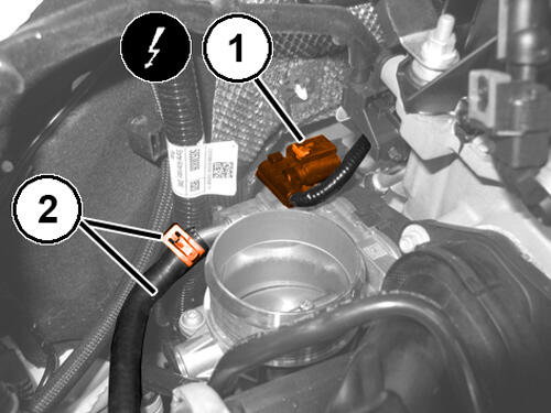
- Disconnect the electrical connection (1) from the throttle body.
- Loosen the band (2) and disconnect the coolant supply pipe from the throttle body.
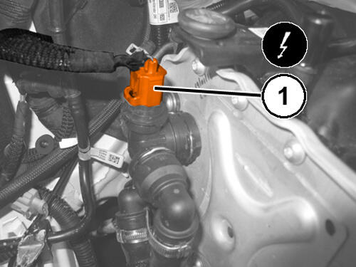
- Disconnect the electrical connection (1) from the charge air cooler coolant temperature sensor.
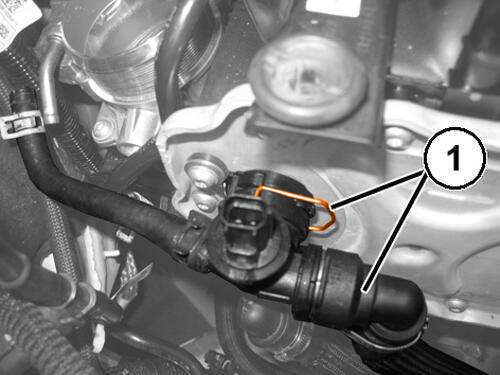
- Retract the clip (1) and disconnect the coolant supply connector from the charge air cooler.
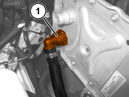
- Disconnect the quick connector (1) and remove the coolant return pipe from the charge air cooler.
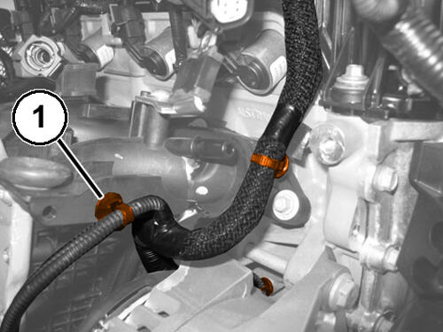
- Release the wiring retaining clips (1).
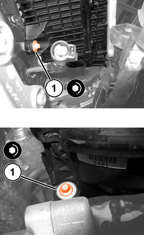
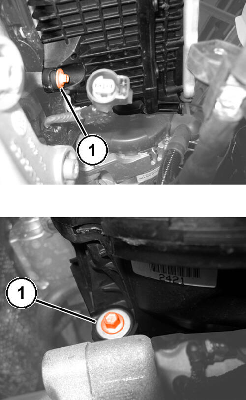
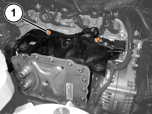
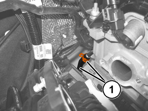
- Remove the two lower screws (1) securing the intake manifold.
- Remove the five upper screws (1) securing the intake manifold and remove it from the cylinder head.
- Loosen the band (1) and disconnect the coolant outlet pipe from the throttle body.
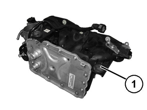
- Remove the intake manifold (1).
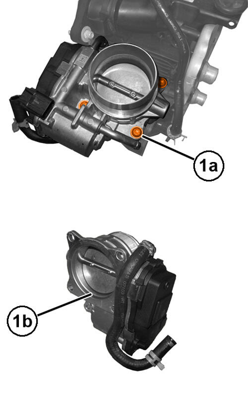
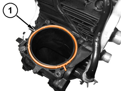
- Remove the screws (1a) and remove the throttle body (1b).
- Remove the throttle body gasket (1).
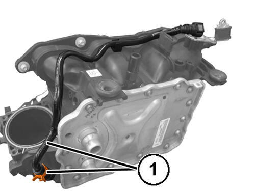
- Loosen the band and remove the fuel vapor pipe (1).
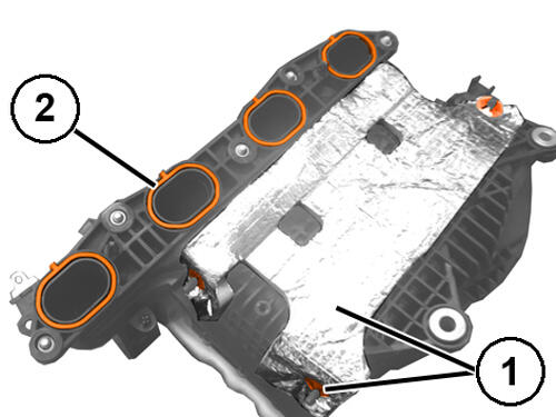
- Remove the toothed washers and remove the heat shield (1).
- Remove the seals (2).
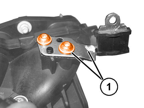
- Remove the screws (1) and remove the fuel vapor solenoid valve support bracket.
INSTALLATION
- Install the fuel vapor solenoid valve support bracket and tighten the screws.
- Install new gaskets on the intake manifold.
- Install the heat shield and tighten the screws.
- Install the fuel vapor pipe in position and close the band.
- Install a new gasket in the throttle body housing.
- Install the throttle body and tighten the fastening screws.
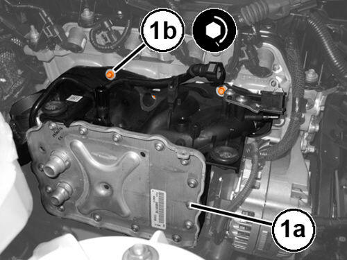
- Install the Intake manifold (1a), connect the coolant outlet pipe to the throttle body and close the retaining band; tighten the five upper screws (1b) to the proper specification Refer to TORQUE SPECIFICATIONS
.
- Tighten the two intake manifold lower screws (1) to the proper specification Refer to TORQUE SPECIFICATIONS .
- Engage the wiring in the retaining clips.
- Connect the quick connector of the coolant return pipe to the charge air cooler.
- Connect the coolant supply pipe to the charge air cooler and engage the retaining clip.
- Connect the electrical connection to the charge air cooler coolant temperature sensor.
- Connect the coolant supply pipe to the throttle body and close the band.
- Connect the electrical connection to the throttle body.
- Install the fuel vapor vacuum solenoid valve. Refer to SOLENOID, EVAPORATIVE EMISSIONS PURGE, REMOVAL AND INSTALLATION .
- Install the front fuel vapor line. Refer to LINES, FUEL VAPOR, REMOVAL AND INSTALLATION .
- Install the intake air pressure/temperature sensor. Refer to SENSOR, TMAP-INTAKE MANIFOLD, REMOVAL AND INSTALLATION .
- Install the Powertrain Control Module (PCM) and PCM mounting bracket. Refer to MODULE, POWERTRAIN CONTROL (PCM), REMOVAL AND INSTALLATION .
- Install the air outlet pipe from turbocharger to throttle body. Refer to COOLER AND HOSES, CHARGE AIR, REMOVAL AND INSTALLATION .
- Install the engine oil vapor intake pipe. Refer to SEPARATOR, OIL, REMOVAL AND INSTALLATION .
- Install the side engine cover. Refer to COVER, ENGINE, REMOVAL AND INSTALLATION .
- Install the air filter housing. Refer to BODY, AIR CLEANER, REMOVAL AND INSTALLATION .
- Install the Mass Airflow (MAF) sensor. Refer to SENSOR, MASS AIRFLOW (MAF), REMOVAL AND INSTALLATION .
- Install the engine belly pan. Refer to BELLY PAN, ENGINE, REMOVAL AND INSTALLATION .
- Install the top engine cover. Refer to COVER, ENGINE, REMOVAL AND INSTALLATION .
- Fill the turbocharger cooling system. Refer to DRAINING AND FILLING THE TURBOCHARGER COOLING SYSTEM .
- Connect the negative battery cable.
- Remove the support and lower the vehicle.