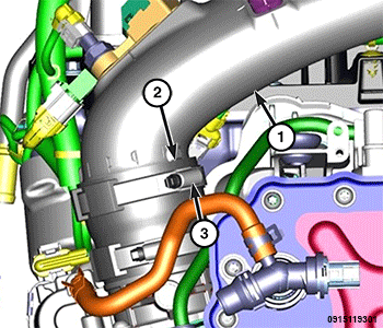
Air Outlet Pipe From Turbocharger To Throttle Body
REMOVAL
- Disconnect and isolate the negative battery cable.
- Remove the top and side engine covers. Refer to COVER, ENGINE, REMOVAL AND INSTALLATION .
- Remove the engine idling oil vapor hose. Refer to SEPARATOR, OIL, REMOVAL AND INSTALLATION .
- Remove the engine oil vapor hose. Refer to SEPARATOR, OIL, REMOVAL AND INSTALLATION .
- Remove the surge valve hose Refer to VALVE, SURGE, REMOVAL AND INSTALLATION .
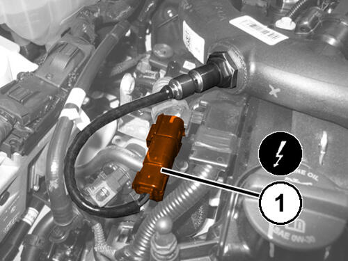
- Disconnect the electrical connection (1) from the oxygen sensor.
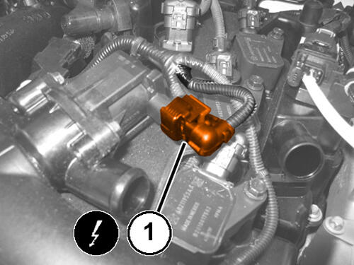
- Disconnect the electrical connection (1) from the charge air cooler temperature control solenoid valve.
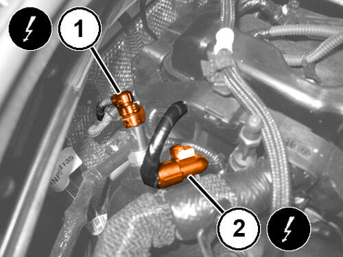
- Disconnect the electrical connection (1) from the air temperature sensor.
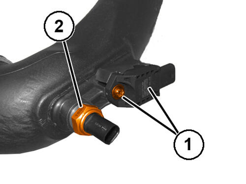
- Disconnect the electrical connection (2) from the air pressure sensor.
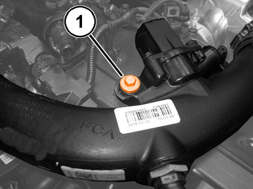
- Remove the bolt (1) securing the turbocharger air outlet pipe to the cylinder head cover.
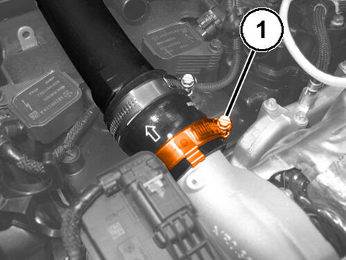
- Loosen the clamp (1) at the turbocharger outlet hose.CAUTION:
Avoid possible damage to the air temperature sensor when the turbocharger air outlet pipe is removed with the sensor still installed in the pipe.
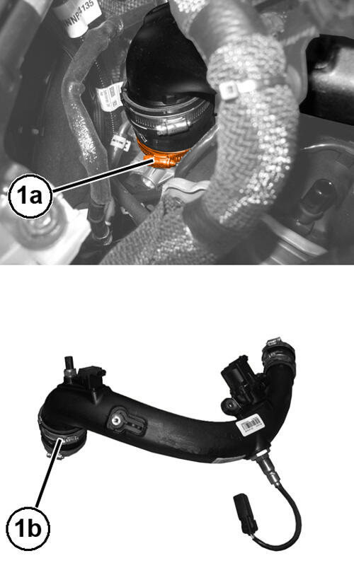
- Loosen the clamp (1a) at the throttle body inlet hose and remove the turbocharger air outlet pipe from the throttle body (1b).
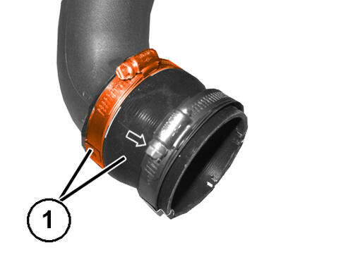
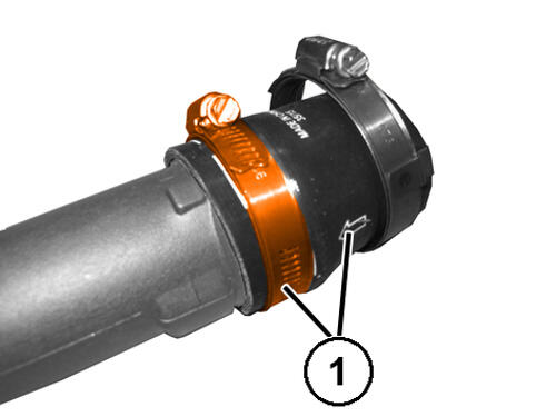
- Loosen the clamp (1) and remove the throttle body air inlet hose from the turbocharger air outlet pipe.CAUTION:
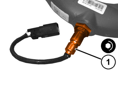
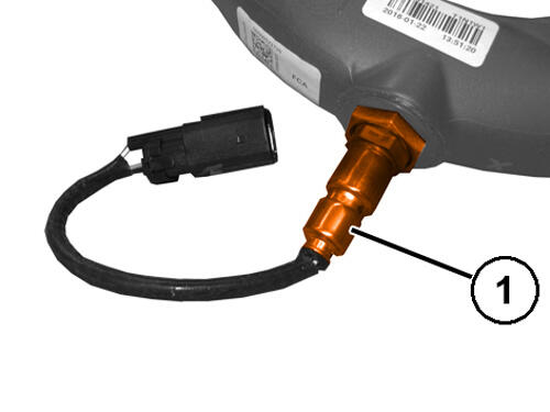
Apply a counter torque to the large hex when removing or installing the O2 sensor to prevent the mounting boss from breaking out of the CAC tube.
- If required, loosen and remove the intake oxygen sensor (1).
- If required, loosen the clamp (1) and remove the turbocharger air outlet hose from the turbocharger air outlet pipe.
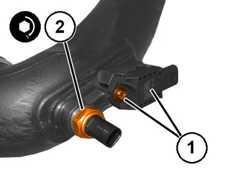
- If required, remove the bolt (1) and remove the air pressure sensor.
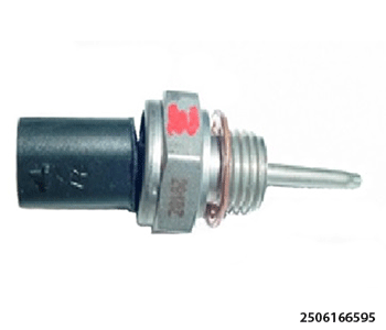
- If required, loosen and remove the air temperature sensor (2).
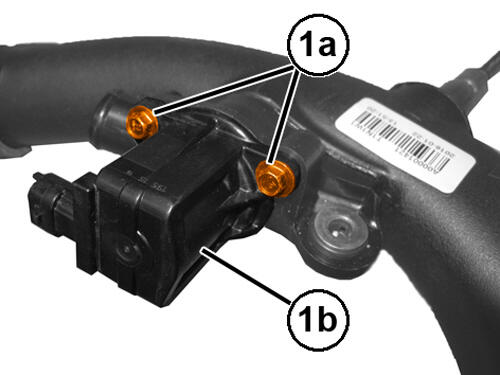
- If required, remove the bolts (1a) and remove the surge valve (1b).
INSTALLATION
- If removed, install the surge valve and tighten the bolts.
- If removed, install the air pressure sensor (1) and tighten the bolt.
- If removed, install the air temperature sensor and tighten it to the proper specification Refer to TORQUE SPECIFICATIONS
.CAUTION:
Apply a counter torque to the large hex when removing or installing the O2 sensor to prevent the mounting boss from breaking out of the CAC tube.
- If removed, install the intake oxygen sensor and tighten it to the proper specification Refer to TORQUE SPECIFICATIONS
.NOTE:
The clamps on the throttle body and turbocharger hoses must be properly tightened to specification. Under or over tightening of the clamps may result in clamp failure and turbocharger air outlet pipe blow-off during engine operation.
- If removed, install the turbocharger air outlet hose (1) to the turbocharger air outlet pipe while aligning the installation arrow on the hose with the rib on the pipe, Tighten the clamp to the proper specification Refer to TORQUE SPECIFICATIONS
.
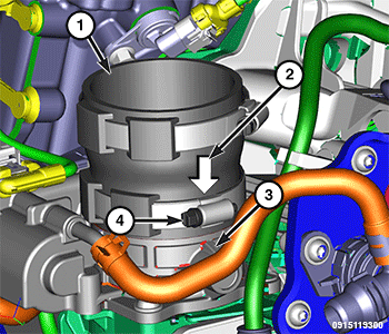
- Push the throttle body air inlet hose (1) onto the throttle body while aligning the installation arrow (2) on the hose with the rib (3) on the throttle body. Tighten the lower clamp (4) to the proper specification Refer to TORQUE SPECIFICATIONS
.
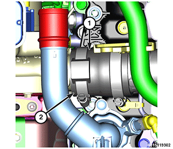
- Push the turbocharger air outlet pipe (1) onto the turbocharger outlet and ensure the air outlet hose is fully seated against the machined stop (2) on the turbocharger outlet. Do not tighten the clamp at this time.
- Rotate the turbocharger air outlet pipe (1) into position and push the pipe into the throttle body air inlet hose until the rib on the pipe (2) reaches the top of the throttle body air inlet hose. Position the upper clamp (3) within the alignment markings on the turbocharger air outlet pipe. Do not tighten the clamp at this time.
- Install the bolt (1) securing the turbocharger air outlet pipe to the cylinder head cover and tighten to the proper specification Refer to TORQUE SPECIFICATIONS .
- Tighten the turbocharger air outlet hose clamp and the throttle body air inlet hose clamp to the proper specification Refer to TORQUE SPECIFICATIONS .
- Connect the electrical connection to the air pressure sensor.
- Connect the electrical connection to the air temperature sensor.
- Connect the electrical connection to the surge valve.
- Connect the electrical connection to the intake oxygen sensor.
- Install the surge valve hose. Refer to VALVE, SURGE, REMOVAL AND INSTALLATION .
- Install the engine oil vapor hose. Refer to SEPARATOR, OIL, REMOVAL AND INSTALLATION .
- Install the engine idling oil vapor hose. Refer to SEPARATOR, OIL, REMOVAL AND INSTALLATION .
- Install the top and side engine covers. Refer to COVER, ENGINE, REMOVAL AND INSTALLATION .
- Connect the negative battery cable.