Description And Operation
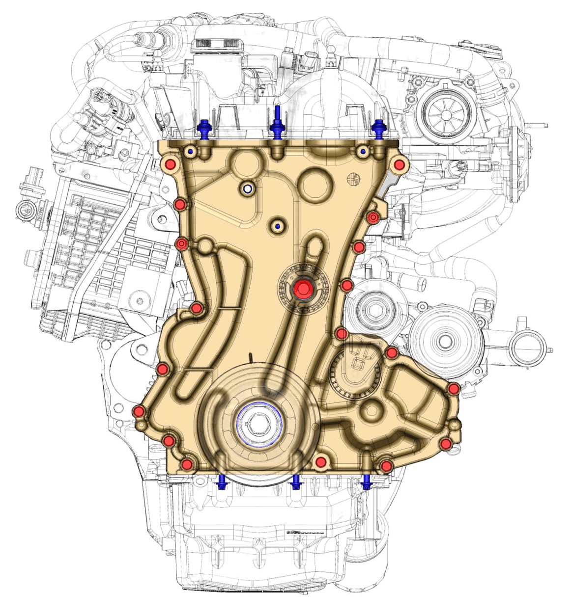
The crankshaft drives the single camshaft through a chain. The timing chain is located under a cover on the accessory drive belt side of the engine.
The timing system cover is fastened to the engine block and the cylinder head (bolts highlighted in red), the cylinder head cover and the oil pan (bolts highlighted in blue).
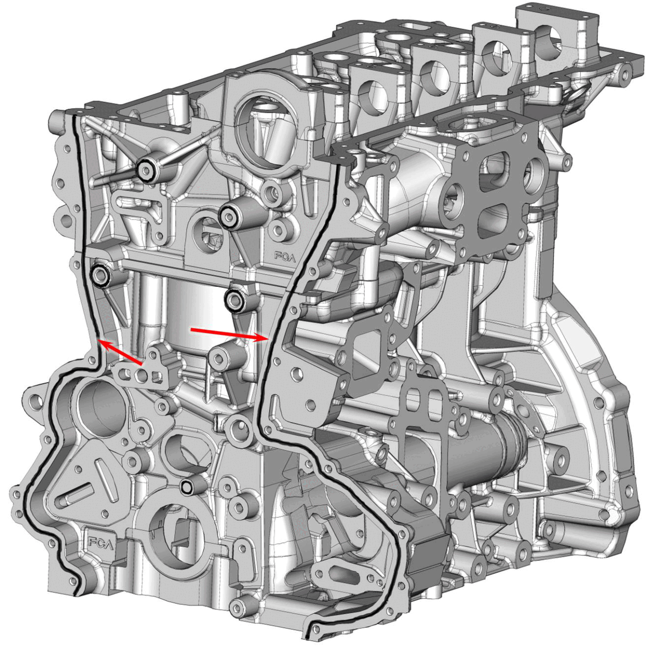
There is sealant applied between the timing cover and the engine to ensure an oil-tight seal.
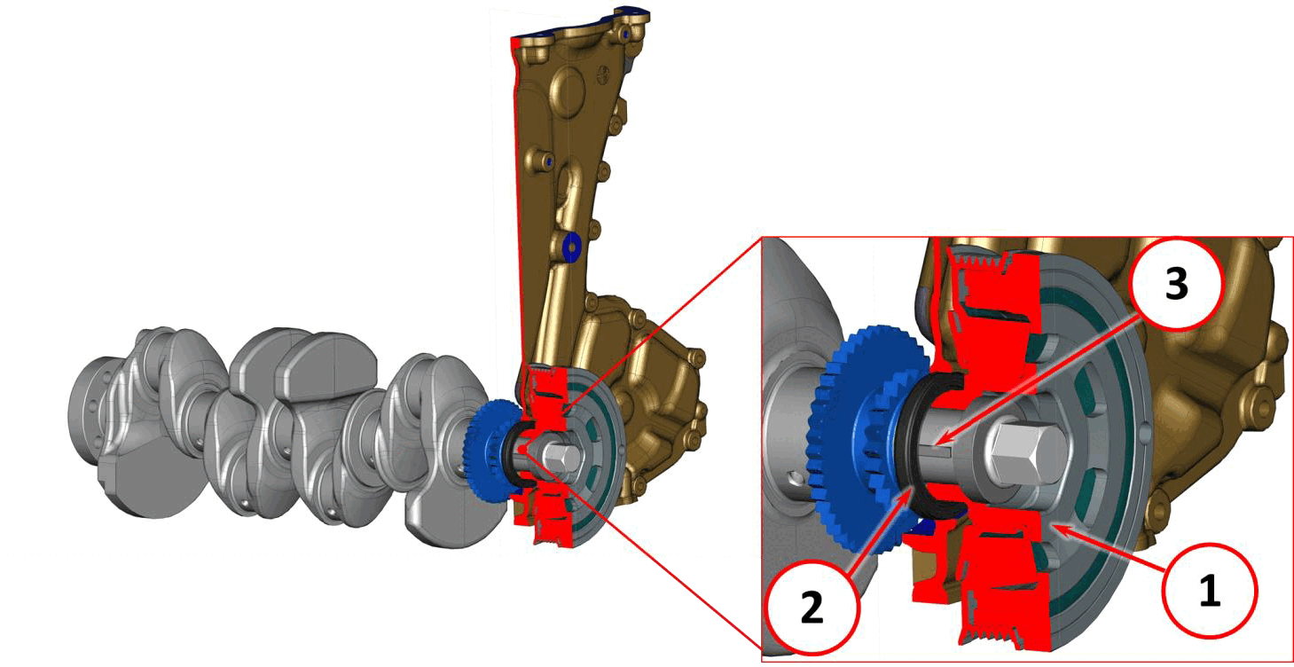
The crankshaft vibration damper (1) is located on the crankshaft with a key (3). There is an oil seal (2) to seal the oil in the space between the crankshaft vibration damper and the timing system cover.
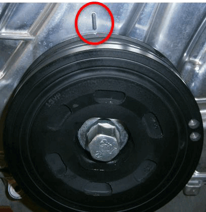
Fixing the position of the crankshaft vibration damper to the crankshaft, allows a reference mark to be placed on the timing system cover, which indicates when the crankshaft is in the position that corresponds to the 1st and 4th cylinders being at Top Dead Center (TDC).
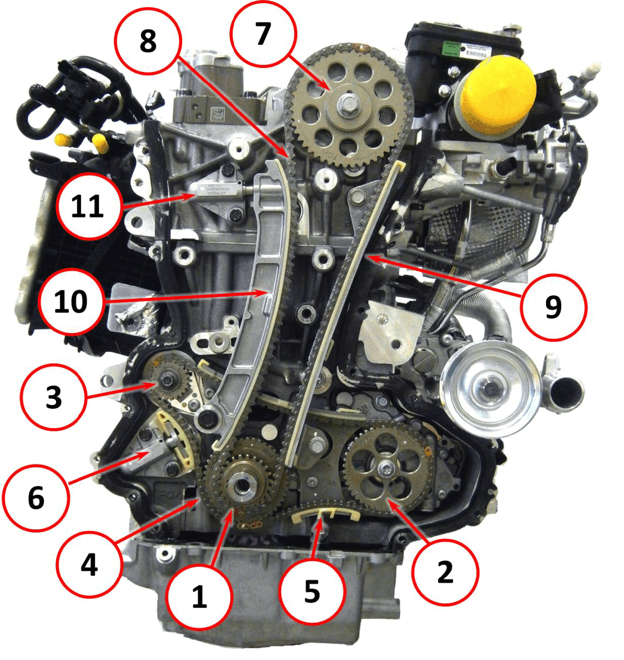
The main components of the valve timing system are:
- Crankshaft sprocket
- Oil pump sprocket
- Right balance shaft sprocket (intake side)
- Oil pump drive chain for the right balance shaft and the oil pump (which, in turn, drives the left balance shaft)
- Oil pump drive chain guide
- Oil pump drive chain tensioner shoe
- Camshaft sprocket
- Cam chain
- Cam chain guide
- Cam chain tensioner arm
- Cam chain tensioner
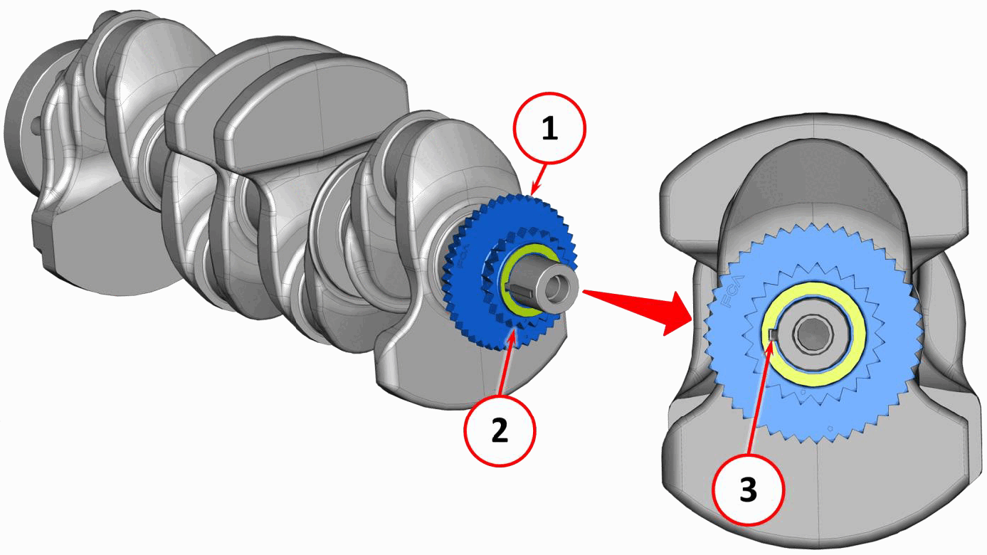
The crankshaft sprocket is a single component that drives both the cam chain and the oil pump chain. It is located on the crankshaft with a key (3). The larger of the two sprockets (1) is dedicated to the cam timing and the smaller sprocket (2) drives the oil pump and the balance shafts.
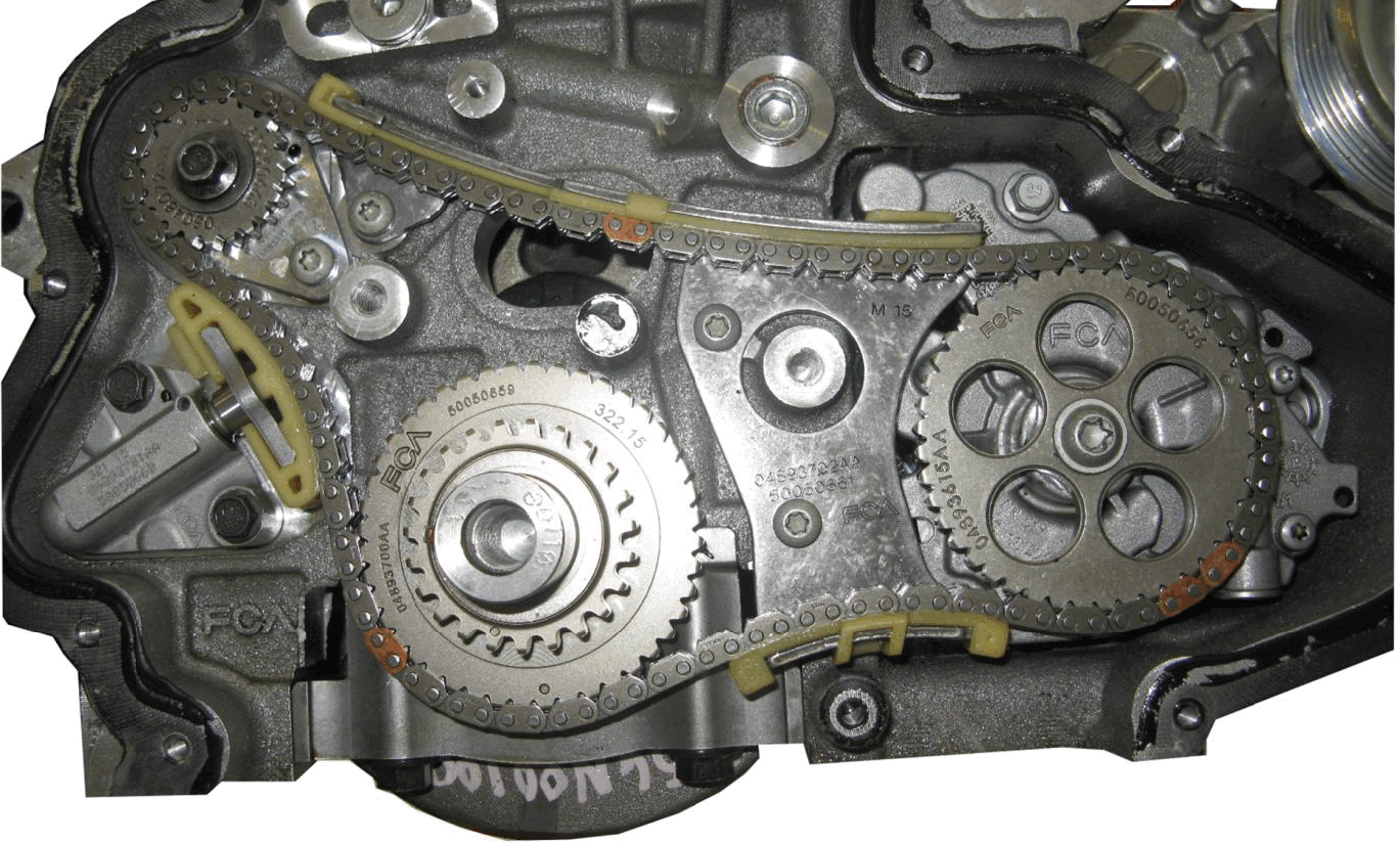
This is the layout of the oil pump drive chain routing between the sprockets for the oil pump and the balance shaft on the right side of the engine.
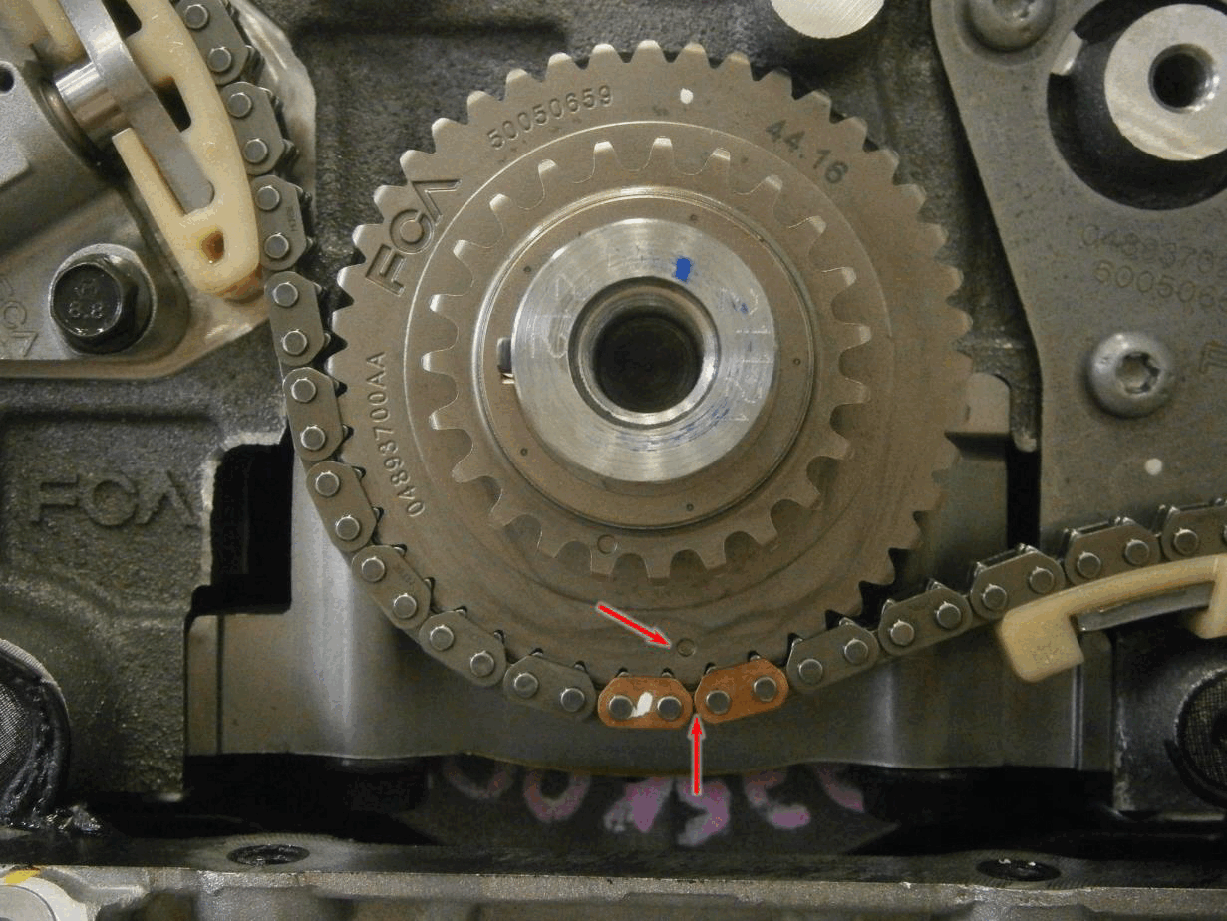
The crankshaft, oil pump and balance shafts must be timed relative to each other. This is accomplished with markings on the sprockets and colored chain links.
The mark on the crankshaft sprocket and the colored chain links must be aligned with the crankshaft in the timing position (1st and 4th cylinders at TDC).
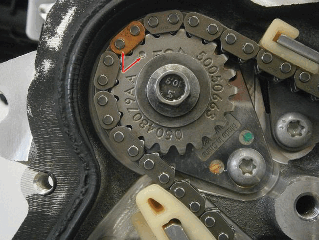
The mark on the right balance shaft sprocket and the colored chain link must also be aligned with the crankshaft at TDC.
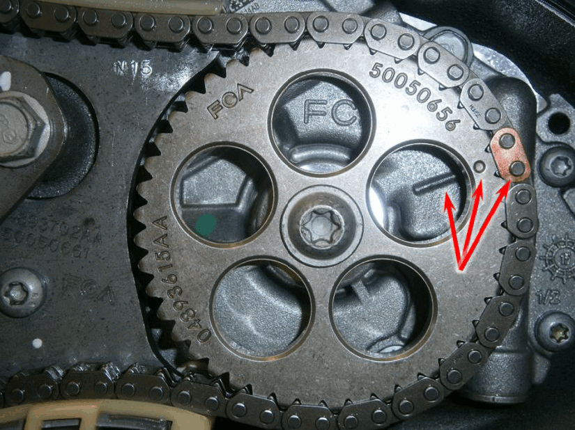
The marks on the oil pump, oil pump sprocket and the colored chain link must also be aligned with the crankshaft at TDC.
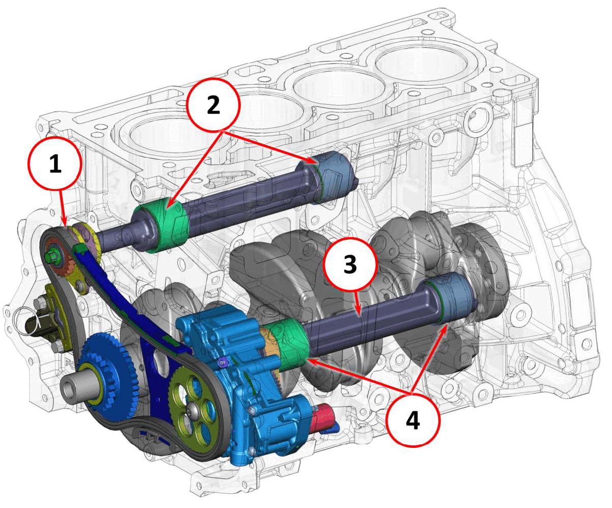
The major components of the balance shafts (right and left) inside the crankcase are:
- Right balance shaft
- Roller bearings with external races
- Left balance shaft
- Roller bearings with external races
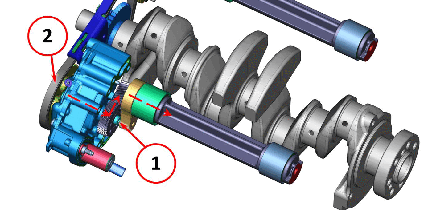
The left balance shaft is driven by a gear fixed to the oil pump shaft (1). The oil pump shaft is driven by the crankshaft through the oil pump drive chain and the oil pump sprocket (2).
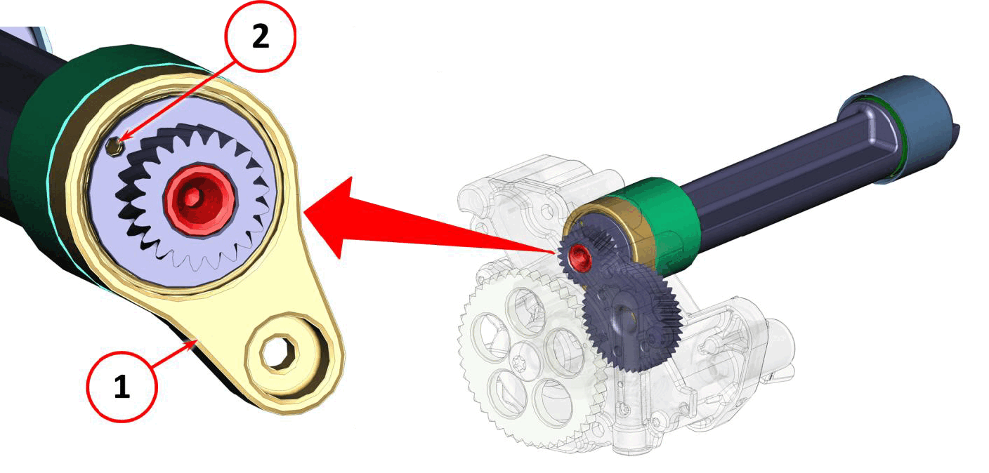
The balance shaft can rotate with respect to the bracket that anchors it to the engine block. To align the balance shaft, the hole (2) on the balance shaft must be aligned with the corresponding hole on the anchoring bracket (1), using a dedicated tool.
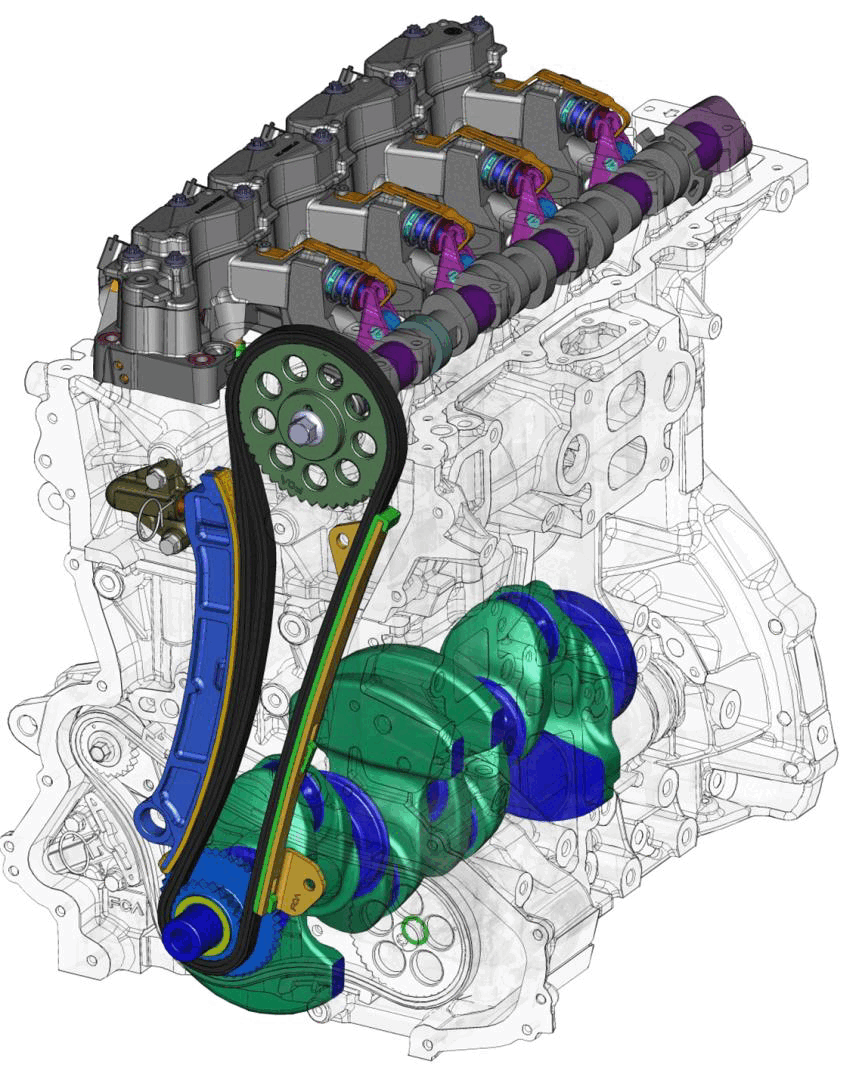
The camshaft is driven by the cam chain, which connects the sprocket on the crankshaft with the sprocket on the camshaft.
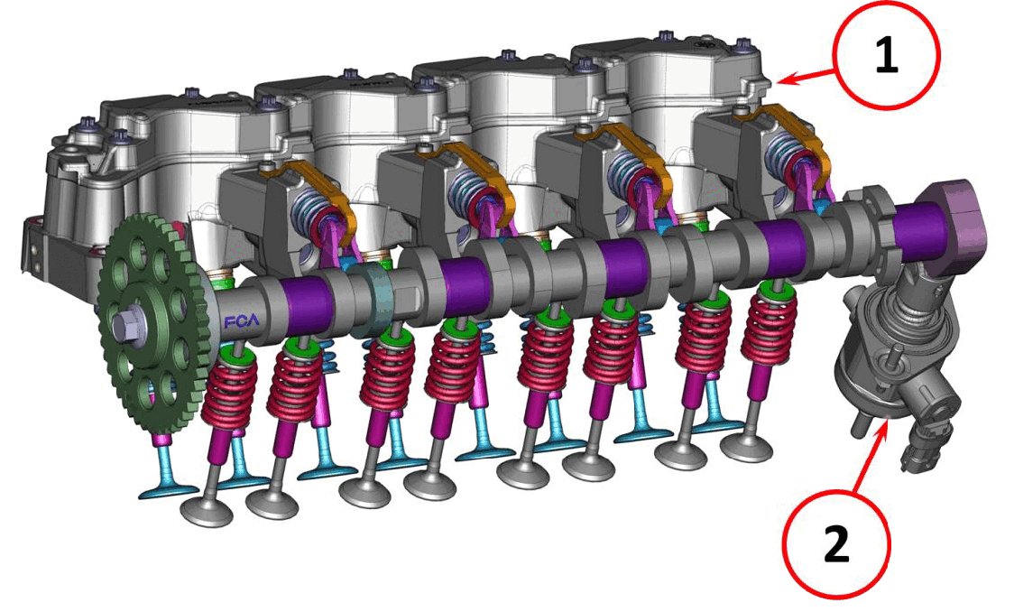
The camshaft rotation opens and closes the exhaust valves (directly through dedicated cam lobes) and the intake valves (indirectly through the MultiAir module (1)). Through a dedicated cam lobe, the camshaft drives the alternating motion of the high pressure fuel pump (2).
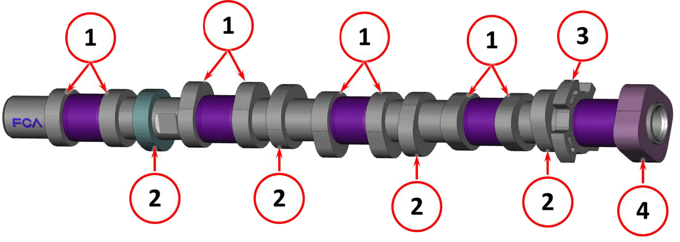
The camshaft is made of steel. The cam lobes are:
- Exhaust cam lobes
- Drive cam lobes for the MultiAir module pump heads
- Target wheel for camshaft position (CMP) sensor reading
- Dedicated cam lobe to drive the high pressure fuel pump
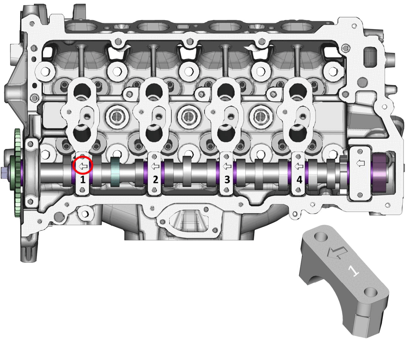
The camshaft is located on the cylinder head with 6 bearing mounts. Five of the bearing mount caps have a cylinder number and an arrow stamped on the upper surface to indicate the correct way to assemble them. The caps must be assembled on the cylinder head with the arrow pointing towards the timing side of the engine.
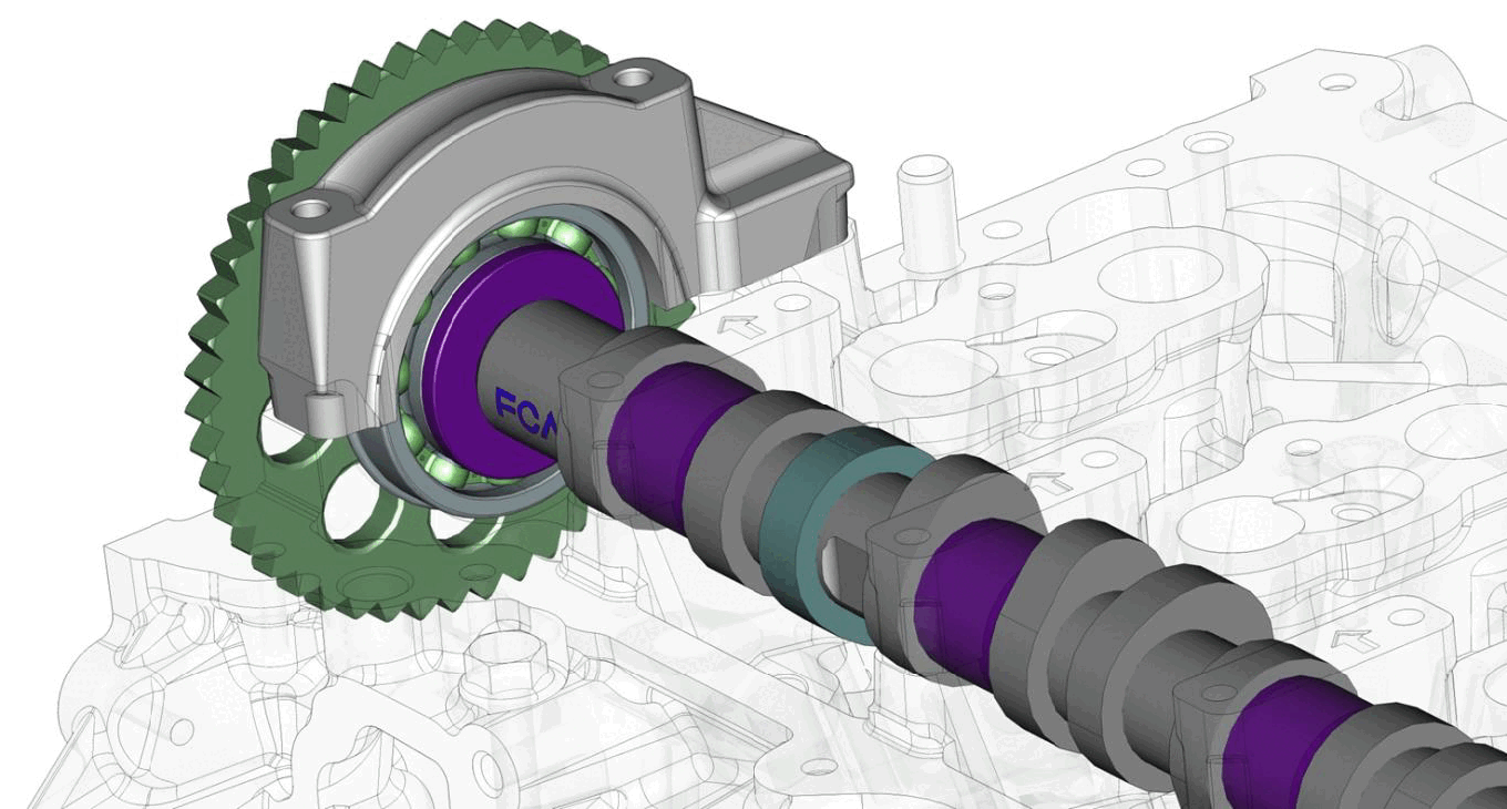
There is a ball bearing between the camshaft and the first mount, held onto the camshaft by interference fit.
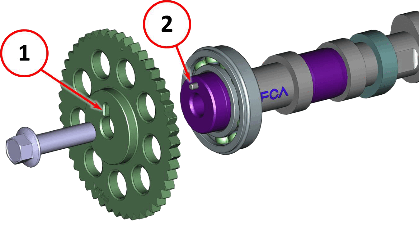
A reference pin (2) locates the sprocket's position relative to the camshaft. It must be inserted into the slot (1) in the sprocket during assembly.
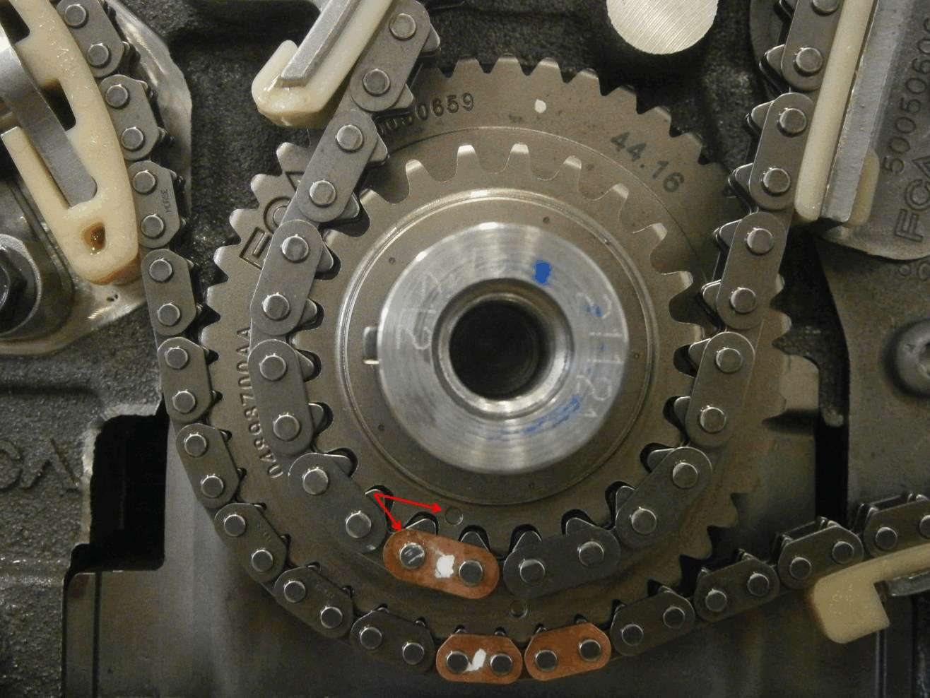
The crankshaft and camshaft must be timed relative to each other. This is accomplished with markings on the sprockets and colored chain links.
The mark on the crankshaft sprocket and the colored chain link must be aligned with the crankshaft in the timing position (1st and 4th cylinders at TDC).
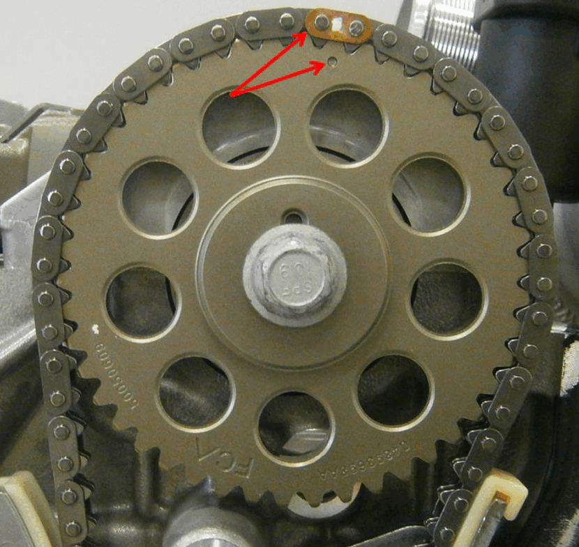
The mark on the camshaft sprocket and the colored chain link must also be aligned with the crankshaft at TDC.
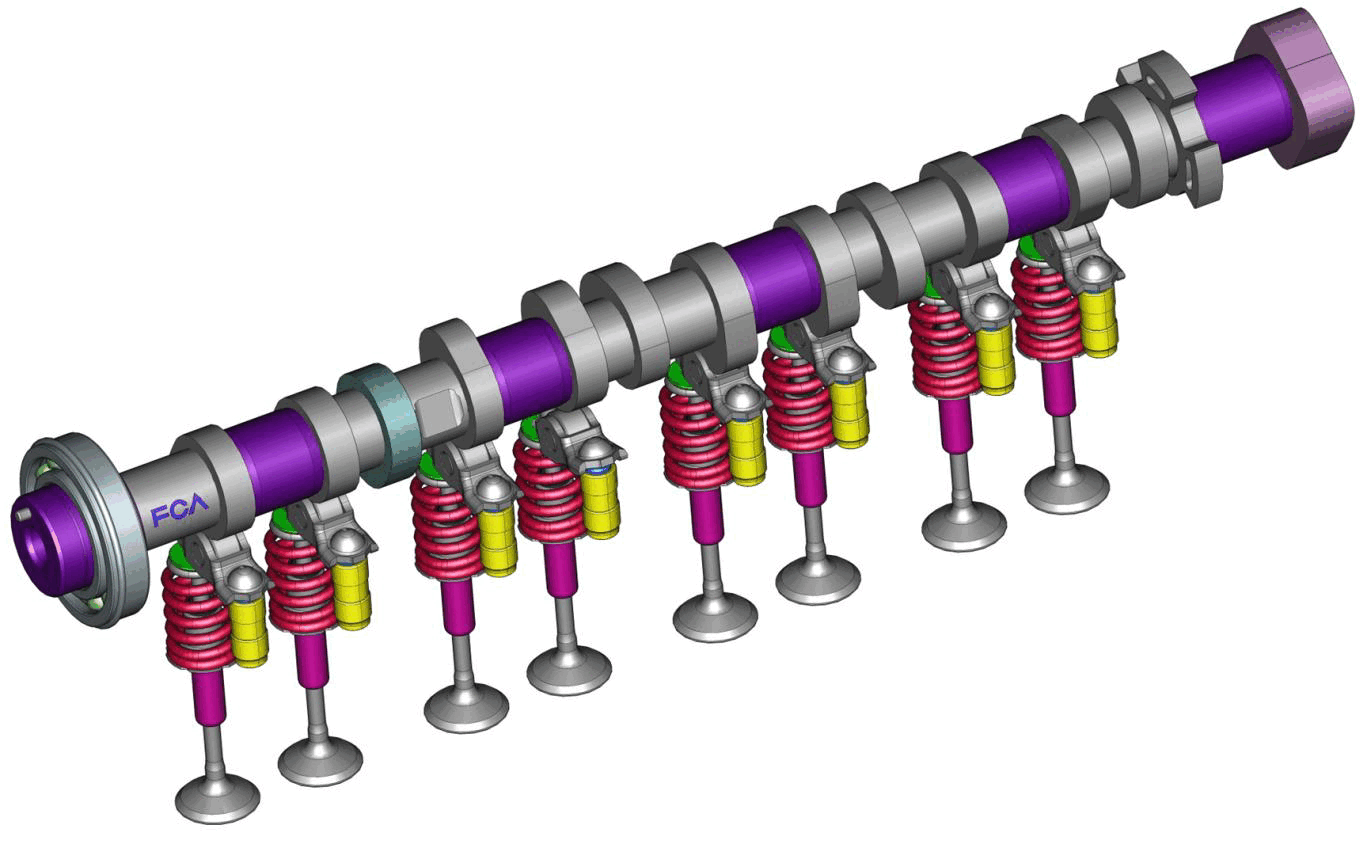
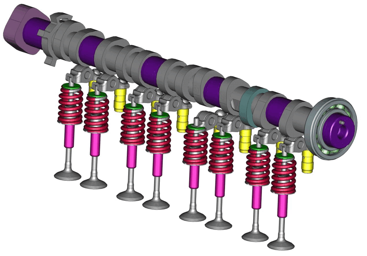
The engine features four valve combustion chambers per cylinder (2 intake and 2 exhaust).
Each exhaust valve is driven by a cam lobe that pushes a rocker arm, one end of which rests on the hydraulic lifter and the other end on the valve.
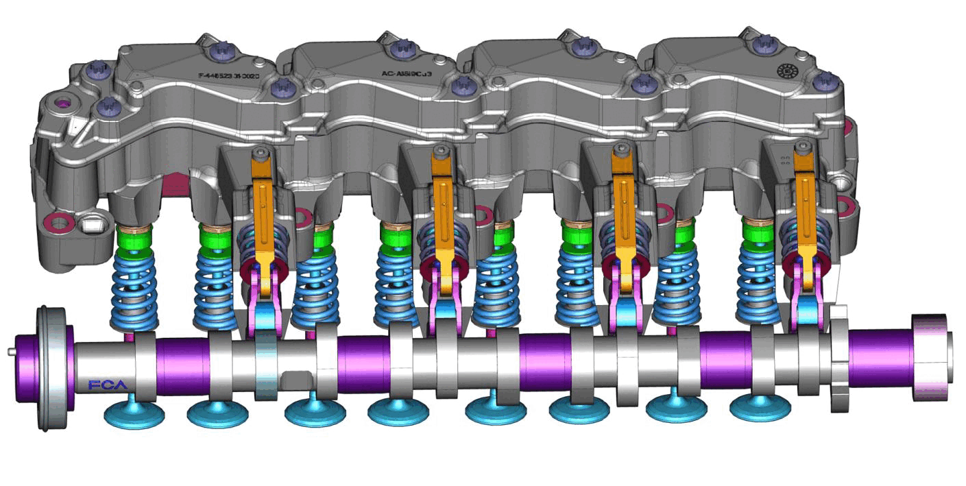
The intake valves are operated by the combined action of the camshaft, the MultiAir module and the electrical controls that the Powertrain Control Module (PCM) sends to the MultiAir solenoid valves.
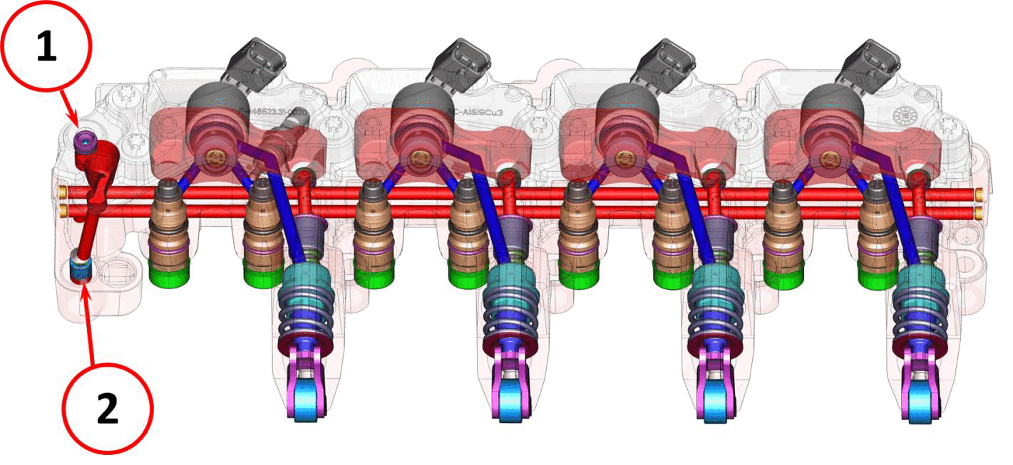
The MultiAir solenoid valves allow the PCM to send the oil flow to the intake valve actuators at the right pressure to lift the valves by the desired amount.
Oil enters the MultiAir module through an oil inlet from the cylinder head (2). The MultiAir module can also be manually filled through an oil filler hole (1).
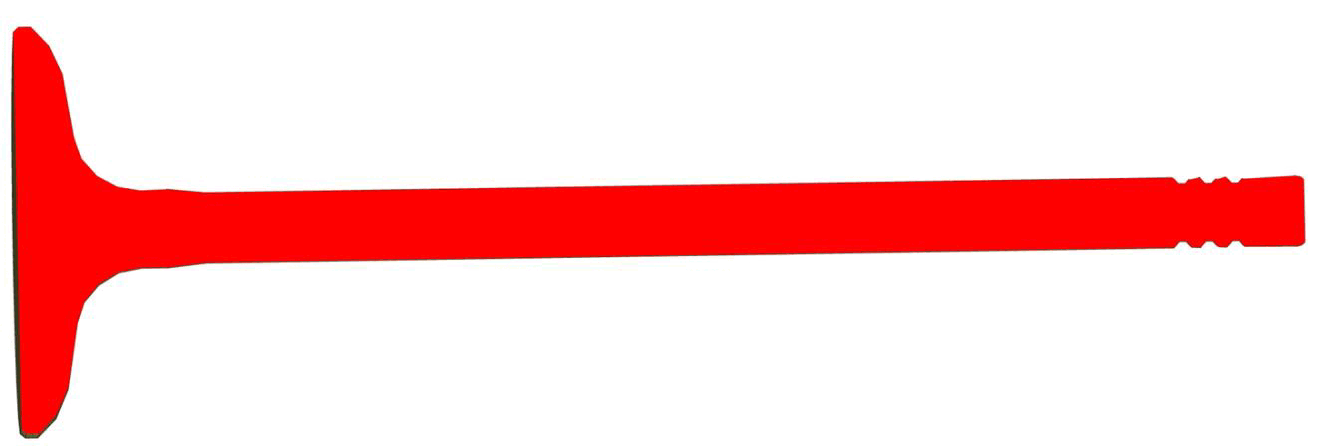
The intake valves are steel and have been subjected to a hardening heat treatment and tempering to increase hardness.
The solid valve stem has a nitriding heat treatment of the surface to obtain the highest levels of hardness.
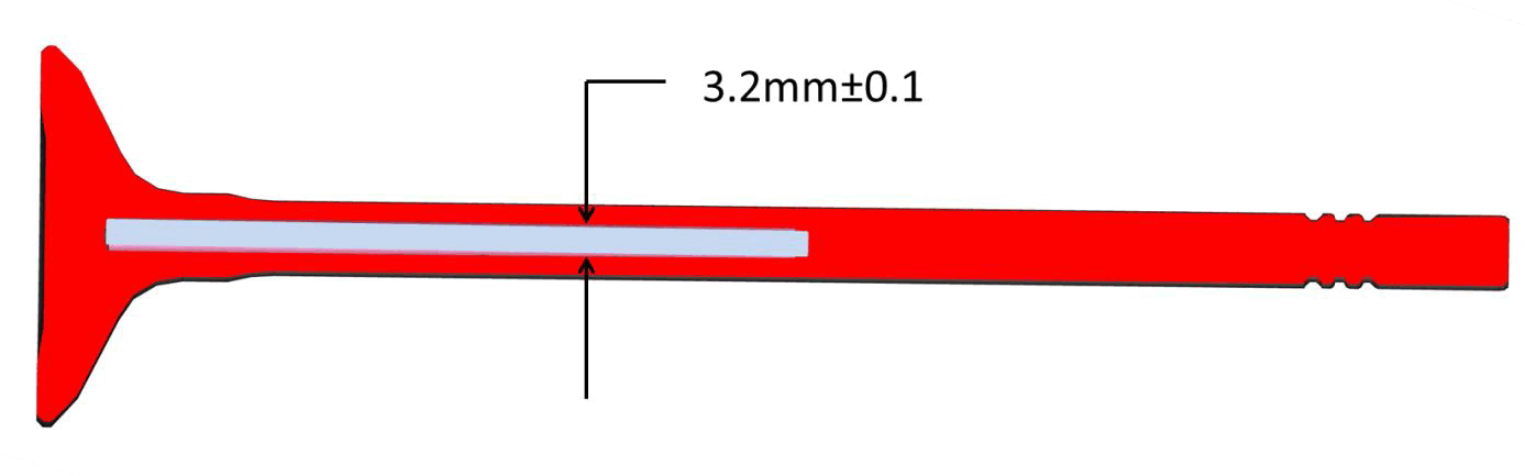
The exhaust valves have to resist higher temperatures than the intake valves and are also subjected to the corrosive effect of exhaust gases. For this reason, the valve head has been made in a different steel alloy than the stem.
The internal cavity of the exhaust valve stem is filled with 45-55% sodium. Sodium becomes liquid at around 100°C (212°F); the liquid sodium allows the heat to be dispersed more efficiently. Sodium in liquid stage moves inside the valve cavity during high alternating motion, transferring part of the high heat from the valve head to the stem (and from there to the cylinder head via the valve guide). In this way, the valve temperature is further reduced.