Engine Timing Chain Cover
REMOVAL
- Raise and support the vehicle. Refer to HOISTING, STANDARD PROCEDURE .
- Disconnect and isolate the negative battery cable.
- Remove the front suspension crossmember with steering gear. Refer to CROSSMEMBER, FRONT SUSPENSION, REMOVAL AND INSTALLATION .
- Drain the engine oil. Refer to FILTER, ENGINE OIL, REMOVAL AND INSTALLATION .
- Remove the oil pan. Refer to PAN, OIL, REMOVAL AND INSTALLATION .
- Temporarily, reinstall the front suspension crossmember without the steering box and tighten the fixing screws to the body.
- Remove the power unit support (1).
- Remove the cylinder head cover. Refer to COVER(S), CYLINDER HEAD, REMOVAL AND INSTALLATION .
- Remove the accessory drive belt. Refer to BELT, SERPENTINE, REMOVAL AND INSTALLATION .
- Remove the accessory drive belt idler pulley. Refer to PULLEY, IDLER, REMOVAL AND INSTALLATION .
- Remove the accessory drive belt tensioner. Refer to TENSIONER, BELT, REMOVAL AND INSTALLATION .
- Remove the accessory drive belt upper guard. Refer to BELT, SERPENTINE, REMOVAL AND INSTALLATION
.
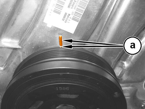
- Rotate the crankshaft clockwise to align the timing cover mark and damper notch (a).
- Remove the vibration damper. Refer to DAMPER, VIBRATION, REMOVAL AND INSTALLATION DAMPER, VIBRATION, REMOVAL AND INSTALLATION
.
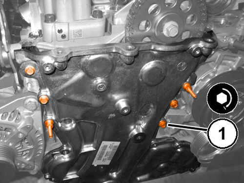
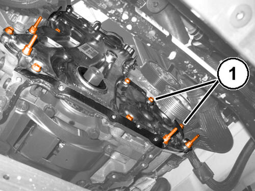
- Remove the timing cover to the crankcase lower screws (1).
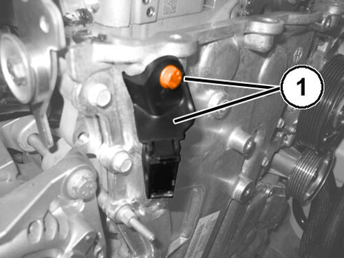
- Remove the screw (1) and remove the fuel vapor pipe mounting bracket.
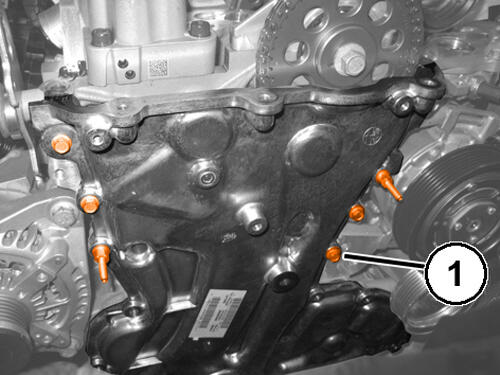
- Remove the timing cover to crankcase upper screws (1).
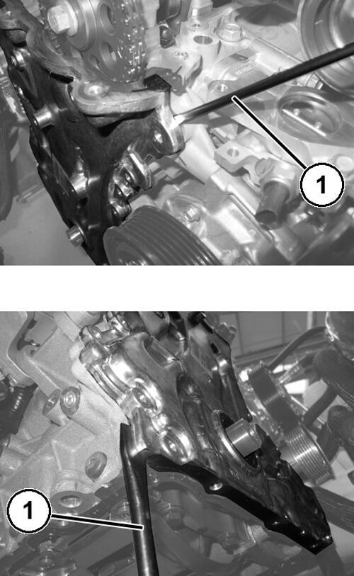
- Using a suitable tool (1), pry on the upper and lower flanges of the timing cover to release it from the sealant.
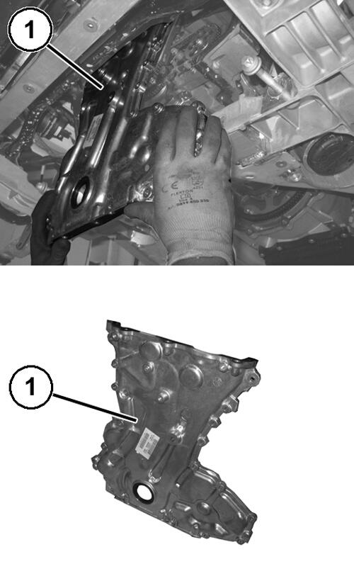
- Remove the timing cover (1) from the locating dowels and the engine crankshaft.
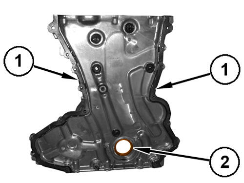
- Remove the sealant residues (1) from the timing chain cover.
- If required, remove the front crankshaft oil seal (2) from the timing chain cover.NOTE:
Be careful not to damage the oil seal seat when removing the seal.
NOTE:The oil seal is ruined during the removal operation so it must always be replaced.
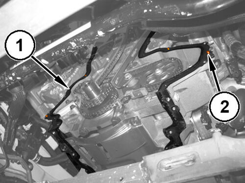
- Remove the sealant residues (1) from the crankcase.
- Check the integrity of the timing chain cover locating dowels (2).
INSTALLATION
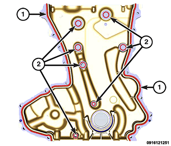
- Clean the engine timing cover, cylinder head and cylinder engine block mating surfaces with isopropyl alcohol in preparation for sealant application.CAUTION:
Engine assembly requires the use of a unique sealant that is compatible with engine oil. Using a sealant other than Mopar® Threebond Engine RTV Sealant may result in engine fluid leakage.
CAUTION:Following the application of Mopar® Threebond Engine RTV Sealant to the gasket surfaces, the components must be assembled within 10 minutes and the attaching fasteners must be tightened to specification within 45 minutes. Prolonged exposure to the air prior to assembly may result in engine fluid leakage.
- Apply a 3 to 4 mm bead of Mopar® Threebond Engine RTV Sealant to the timing chain cover flange (1).
- Apply a 2 to 3 mm bead of Mopar® Threebond Engine RTV Sealant to the perimeter of the seven holes (2) present in the central zone of the timing chain cover.NOTE:
The bead of sealant must be uninterrupted.
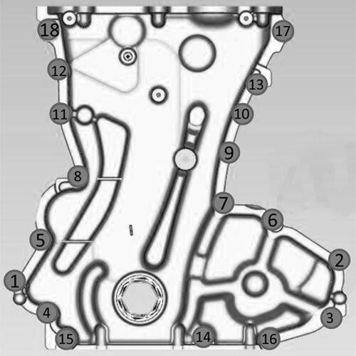
- Install the timing chain cover by engaging the locating dowels and tighten the screws (1) in the sequence shown to the proper specification Refer to TORQUE SPECIFICATIONS
.
NOTE:
Tighten the timing chain cover screws following the order shown in the illustration.
- Install the fuel vapor pipe support bracket and tighten the screw.
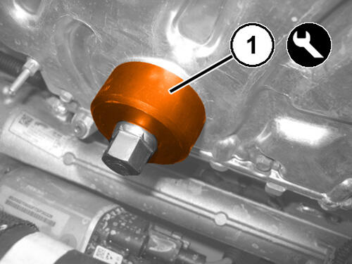
- If removed, install a NEW front crankshaft oil seal in the timing chain cover using (special tool #9506, Installer, Oil Seal) (1).
- Install the vibration damper. Refer to DAMPER, VIBRATION, REMOVAL AND INSTALLATION .
- Install the accessory drive belt upper guard. Refer to BELT, SERPENTINE, REMOVAL AND INSTALLATION .
- Install the accessory drive belt tensioner. Refer to TENSIONER, BELT, REMOVAL AND INSTALLATION .
- Install the accessory drive belt idler pulley. Refer to PULLEY, IDLER, REMOVAL AND INSTALLATION .
- Install the accessory drive belt. Refer to BELT, SERPENTINE, REMOVAL AND INSTALLATION .
- Install the cylinder head cover. Refer to COVER(S), CYLINDER HEAD, REMOVAL AND INSTALLATION .
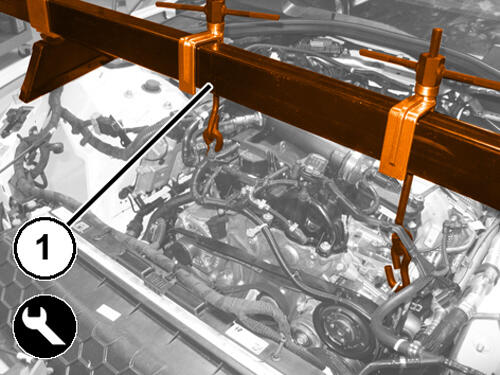
- Install the (special tool #8534C, Fixture, Driveline Support) (1).
- Undo the bolts and remove the front suspension crossmember fitted temporarily without the steering box.
- Install the oil pan. Refer to PAN, OIL, REMOVAL AND INSTALLATION .
- Install the front suspension crossmember with steering gear. Refer to CROSSMEMBER, FRONT SUSPENSION, REMOVAL AND INSTALLATION .
- Remove the power unit support.
- If removed, install the oil filter and fill the engine crankcase with the proper oil to the correct level. Refer to CAPACITIES AND RECOMMENDED FLUIDS, SPECIFICATIONS .
- Connect the negative battery cable.
- Remove the support and lower the vehicle.