Removal And Installation: Removal
- Raise and support the vehicle. Refer to HOISTING, STANDARD PROCEDURE .
- Disconnect and isolate the negative battery cable.
- Remove tire and wheel assembly. Refer to REMOVAL AND INSTALLATION
.
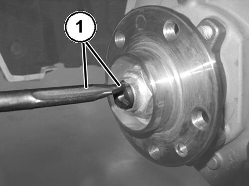
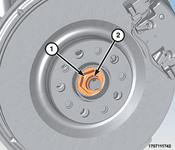
- Using a suitable punch, lift the two staked areas on the hub nut (1) to avoid damaging the halfshaft.
- While a helper applies the brakes to keep the hub from rotating, remove the hub nut (1) from the halfshaft and DISCARD it. The hub nut is not reusable
- Remove the rear brake rotor. Refer to ROTOR, BRAKE, REMOVAL AND INSTALLATION .
- Remove the three brake rotor shield to knuckle screws and remove the brake rotor shield.
- Remove the rear spring. Refer to SPRING(S), REMOVAL AND INSTALLATION .
- Remove the rear shock absorber. Refer to SHOCK ABSORBER, SUSPENSION, REMOVAL AND INSTALLATION .
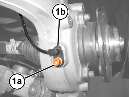
- Remove the wheel speed sensor (1b) to knuckle mounting bolt (1a), and remove the wheel speed sensor from the knuckle.
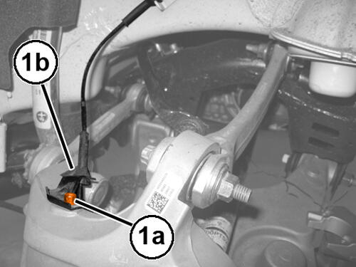
- Remove the wheel speed sensor bracket (1b) to knuckle mounting bolt (1b), and carefully position the wheel speed sensor and bracket to the side.NOTE:
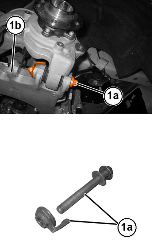
The bolt consists of a screw with a special rosette and a nut with an anti-rotation cage.
- Remove the knuckle to lower control arm (1b) mounting bolt (1a)
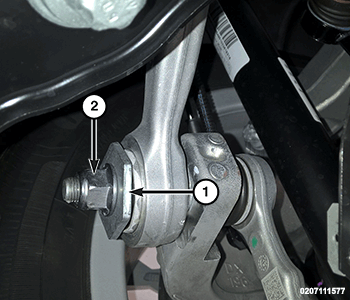
- Remove the toe link to knuckle mounting nut (2), and remove the toe link and the tension link from the vehicle.
- Lower the hydraulic lift positioned under the lower wishbone arm.
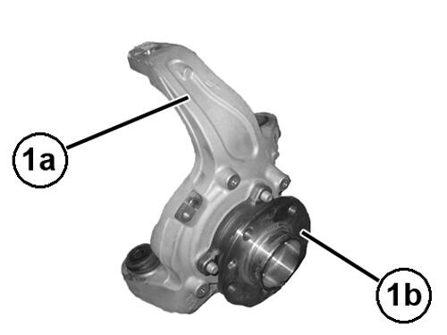
- Remove the knuckle (1a) with the hub and bearing (1b), disengaging the driveshaft from the knuckle.